4-Bit Binary Counter Using Multi-Function Shield
HARDWARE REQUIRED:
- PICUNO Microcontroller board
- 1 × Multi-Function Shield
- USB cable
DESCRIPTION:
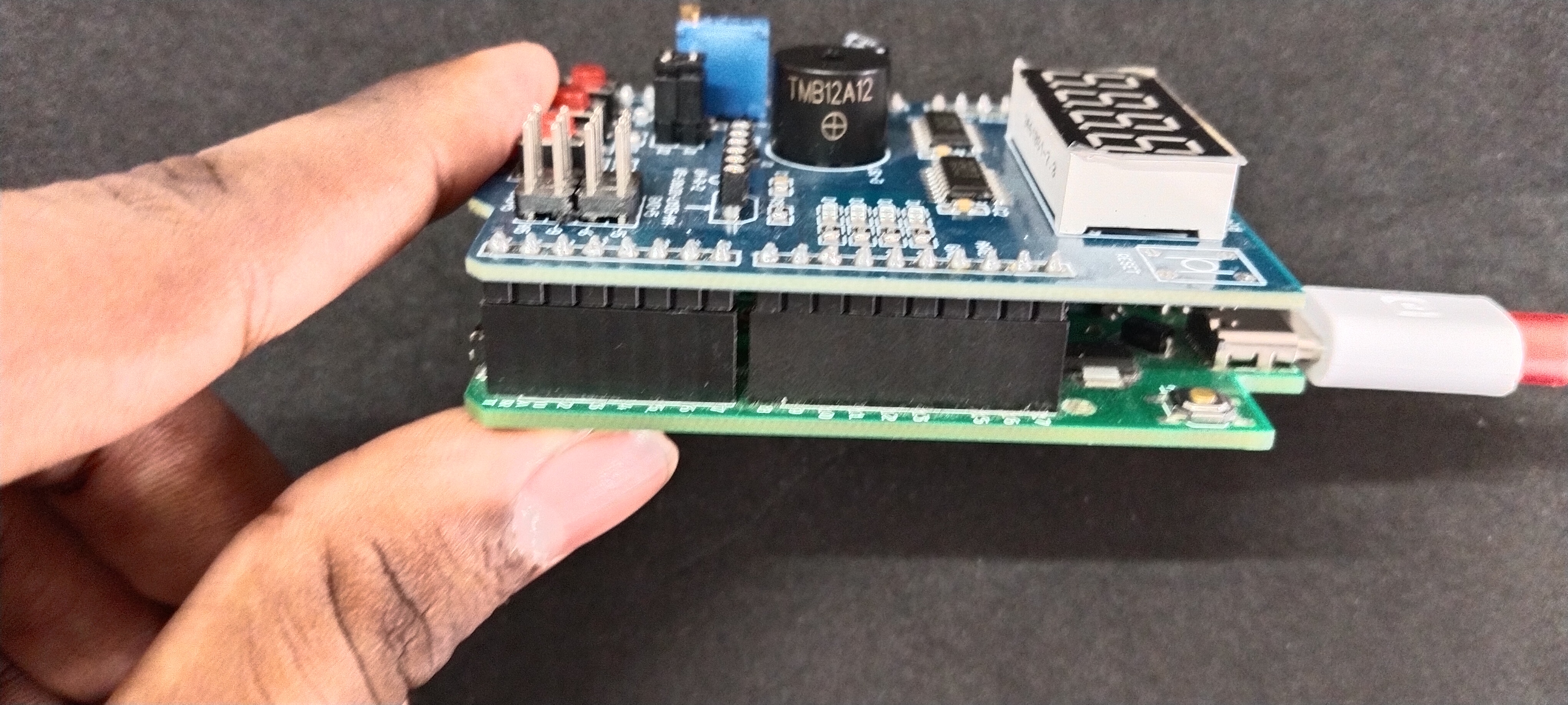
This project demonstrates the use of a Multi-function Shield, which is a pre-built circuit board that contains common components like LEDs, buttons, potentiometer, buzzer and shift registers already wired to specific pins. Using a shield like this simplifies the hardware setup by eliminating the need for a breadboard and individual jumper wires, allowing you to focus directly on the programming logic.
The program turns the four onboard LEDs of the shield into a 4-bit binary display. The user can control a number from 0 (binary 0000) to 15 (binary 1111) using the three push buttons. One button increases the count, another decreases it, and the third resets it to zero.
The program turns the four onboard LEDs of the shield into a 4-bit binary display. The user can control a number from 0 (binary 0000) to 15 (binary 1111) using the three push buttons. One button increases the count, another decreases it, and the third resets it to zero.
- Plug the Multi-function Shield directly on top of the PICUNO board. The shield's components have fixed connections to the board's pins.
- LEDs (D1-D4) are connected to GPIO 13, 12, 11, and 10.
- Buttons (S1-S3) are connected to Analog Pins A1, A2, and A3.
SCHEMATIC:
No external wiring is required. Place the Multi-Function shield directly on top of the PICUNO board.
Multi-Function shield:
LEDs (D1-D4) → GPIO 13, 12, 11, 10.
Buttons (S1-S3) → A1, A2, A3.
CODE -- C:
displayBinary() function - This is the core of the visual output. It takes a number (from 0 to 15) and uses bitwise operations (>> and &) to check each of the four bits. It then sets the corresponding LED pin LOW (on) or HIGH (off) to display the number in binary.
INPUT_PULLUP - This command in setup() configures the button pins as inputs and activates a small internal resistor that keeps their signal stable. This is why the code checks for a LOW signal to detect a press.
millis() Timer - This is the key to the debouncing fix. The millis() function returns the number of milliseconds since the board started. It's used to create a non-blocking timer.
Debounce Logic - The line if ((millis() - lastDebounceTime) > debounceDelay) is the most important part of the fix. It ensures the code only listens for a new button press if 200 milliseconds have passed since the last valid press was registered.
CODE -- PYTHON:
Pin(..., Pin.IN, Pin.PULL_UP) - Configures the button pins as inputs and activates internal pull-up resistors, which keeps the signal stable. The code then looks for a 0 to detect a press.
display_binary() function - This is the core logic. It takes a number (0-15) and uses bitwise operations (>> and &) to check each of the four bits. It then turns the corresponding LED on or off.
Active Low LEDs - On this shield, the LEDs turn ON when the pin is set to low(). The display_binary function is written to handle this.
State Change Detection - The logic if inc_state == 0 and last_inc_state == 1: is used for each button to detect a "rising edge." This ensures that one long button press only registers as a single event.