Smart Alarm Clock
HARDWARE REQUIRED:
- PICUNO Microcontroller board
- 1 × 16x2 I2C LCD Display
- 1 × DS1302 Real Time Clock Module
- 1 × DHT11 Temperature and humidity sensor
- 1 × Rotary Encoder Module
- 1 × Buzzer
- USB cable
- 1 × 4xAA Battery Pack (for external supply)
DESCRIPTION:
This project creates a multi-function smart alarm clock. By default, it displays the live time and date from a Real-Time Clock (RTC) module. The user can press the rotary encoder's button to cycle through different modes: a "weather station" that displays live temperature and humidity from a DHT11 sensor, and an "alarm set" mode. In alarm set mode, the rotary encoder knob is used to adjust the hour and minute for the alarm. When the real time matches the alarm time, a buzzer sounds continuously and a "TIME'S UP" message is displayed until the user presses the button to dismiss it.
LIBRARIES REQUIRED:
For C / Arduino IDE:
dht.h: Manages dht11 sensor.
Wire.h: Manages I2C communication (usually included by default).
LiquidCrystal_I2C.h: The driver library for the I2C LCD module.
For Micropython / Thonny IDE:
dht11.py: The custom library file for the dht11 sensor, saved to the PICUNO board.
i2c_lcd.py: The custom library file saved to the PICUNO board.
The code also uses the built-in machine and time modules.
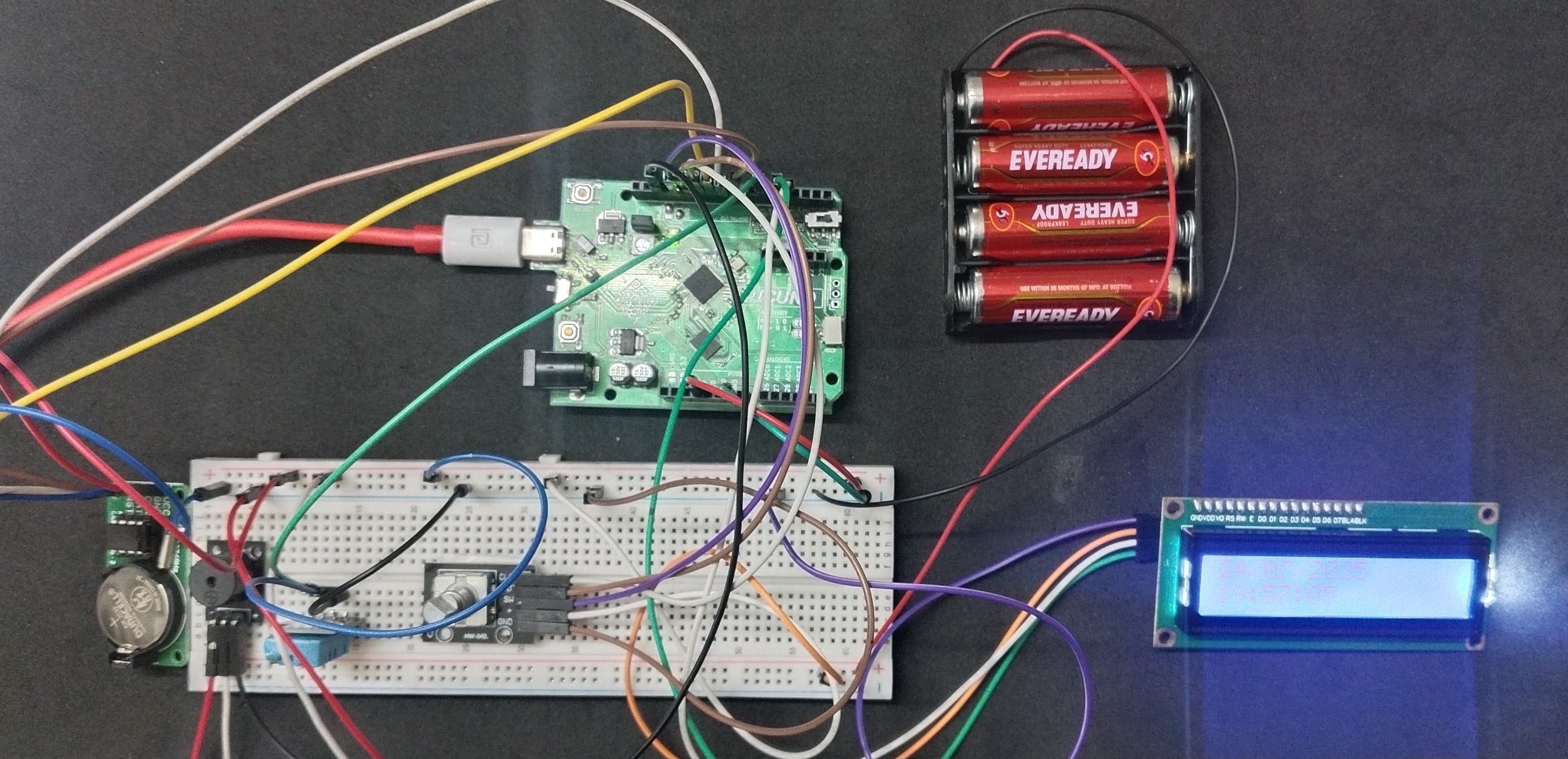
CIRCUIT DIAGRAM:

- Connect the LCD Module's GND pin to GND.
- Connect the LCD Module's VCC pin to the Positive (+) terminal of the 4xAA Battery Pack.
- Connect the LCD Module's SDA pin GPIO 4 (SDA Pin on PICUNO).
- Connect the LCD Module's SCL pin GPIO 5 (SCL Pin on PICUNO).
- Connect the negative terminal (-) of the 4xAA Battery Pack to Common GND on breadboard.
- Connect the VCC pin to 3.3V pin on the board.
- Connect the GND pin to GND pin on board.
- Connect the CLK pin to GPIO 8.
- Connect the DAT pin to GPIO 9.
- Connect the RST pin to GPIO 10.
- Connect the VCC (+) pin to 3.3V pin on the board.
- Connect the GND pin to GND pin on board.
- Connect the CLK pin to GPIO 11.
- Connect the DT pin to GPIO 12.
- Connect the SW pin to GPIO 13.
- Connect the VCC (+) pin to 3.3V pin on the board.
- Connect the GND (-) pin to GND pin on board.
- Connect the Signal (S) pin to GPIO 6.
- Connect the GND (-) pin to GND pin.
- Connect the VCC (+) pin to 5V.
- Connect the Signal (S) pin to GPIO 15.
SCHEMATIC:
16x2 I2C LCD Display:
LCD VCC → 5V
LCD GND → GND
LCD SDA → GPIO 4 (Board SDA Pin)
LCD SCL → GPIO 5 (Board SCL Pin)
DS1302 RTC Module:
VCC → 3.3V
GND → GND
CLK → GPIO 8
DAT → GPIO 9
RST → GPIO 10
Rotary Encoder Module:
VCC → 3.3V
GND → GND
CLK → GPIO 11
DT → GPIO 12
RST → GPIO 13
DHT11 Temperature and Humidity Sensor:
VCC / + → 3.3V
GND / - → GND
Signal / S → GPIO 6
Buzzer Module:
VCC / (+) → 5V
GND / (-) → GND
Signal (S) → GPIO 15
Common Ground Connection:
4xAA Battery Pack (-) → PICUNO Board GND
CODE -- C:
enum Mode - This creates a set of named integer constants (e.g., MODE_CLOCK, MODE_WEATHER). This is used to build a state machine, which makes the code for managing the different menus much cleaner and more readable than using simple numbers.
Manual RTC Functions (read_time, get_reg, etc.) - This group of functions replaces an external library. They handle the low-level, bit-by-bit communication required to send commands and read data directly from the DS1302 RTC chip.
Manual Encoder Logic - The code in the main loop() that checks digitalRead(ENCODER_CLK_PIN) and digitalRead(ENCODER_DT_PIN) is the manual "polling" method for the rotary encoder. It determines the direction of rotation by comparing the states of the two pins when a change is detected.
Helper Functions (update_display, sound_alarm, etc.) - The code is organized into logical blocks for different tasks. This makes the main loop() easier to read and separates the logic for displaying information from the logic for handling inputs.
CODE -- PYTHON:
Manual Control Functions - The code does not use external libraries for the RTC or Rotary Encoder. Instead, it includes low-level functions like _read_byte() and read_time() to communicate directly with the RTC chip, and it "polls" the encoder pins in the main loop to detect rotation.
State Machine (current_mode) - A global variable that tracks which mode the clock is in (displaying time, weather, or setting the alarm). The rotary encoder button is used to cycle through these states.
is_alarming flag - This boolean variable creates a special "alarm" state. When triggered, the main loop is trapped in a section that sounds the buzzer and waits for a button press, ignoring all other functions until the alarm is dismissed.
Non-Blocking Logic (ticks_ms) - Timers based on ticks_ms() are used to refresh the screen and check for the alarm condition once per second, without using long sleep() commands that would make the program unresponsive.