Infinite Loop Robot Car
HARDWARE REQUIRED:
- PICUNO Microcontroller board
- 1 × 2-Wheel Chassis (with wheels, motors, etc.) full set
- 1 × 298N Motor Driver
- 1 × 4xAA Battery pack (with fresh or rechargeable batteries)
- 1 × 9V Battery (optional for external power supply to PICUNO)
- Jumper wires
- USB cable
DESCRIPTION:
This project is the fundamental starting point for any mobile robot. The program commands the robot to perform a simple, repeating sequence of movements: it drives forward for a set duration, stops, drives in reverse, and stops again. This sequence will loop infinitely until the power is removed. This project's main purpose is to test the core functionality of the robot's drive system, ensuring the motors, driver, and power supply are all wired correctly and working together.
ASSEMBLY OF 2-WHEEL CHASIS KIT:
1.) Prepare the Chassis: If your chassis parts are acrylic, they often come with a protective paper or plastic film. Peel this film off all the pieces.
2.) Mount the Motors: Attach the two yellow DC motors to the main chassis plate. Use the brackets and long screws/nuts that came with the kit to secure them firmly in place.
3.) Attach the Wheels: Push the two main wheels onto the plastic shafts of the motors. They should be a snug fit.
4.) Attach the Caster Wheel: Mount the third, free-spinning wheel (the caster or ball wheel) to the other end of the chassis. This wheel acts as the front or back support and allows the robot to turn easily.
5.) Mount the Battery Holder: Use screws to attach the 4xAA battery pack at the bottom of the chassis.
6.) Mount the Electronics: Finally, mount the PICUNO and the L298N motor driver board onto the chassis, usually using screws/double tape. Position them such that to easily run wires to the motors.
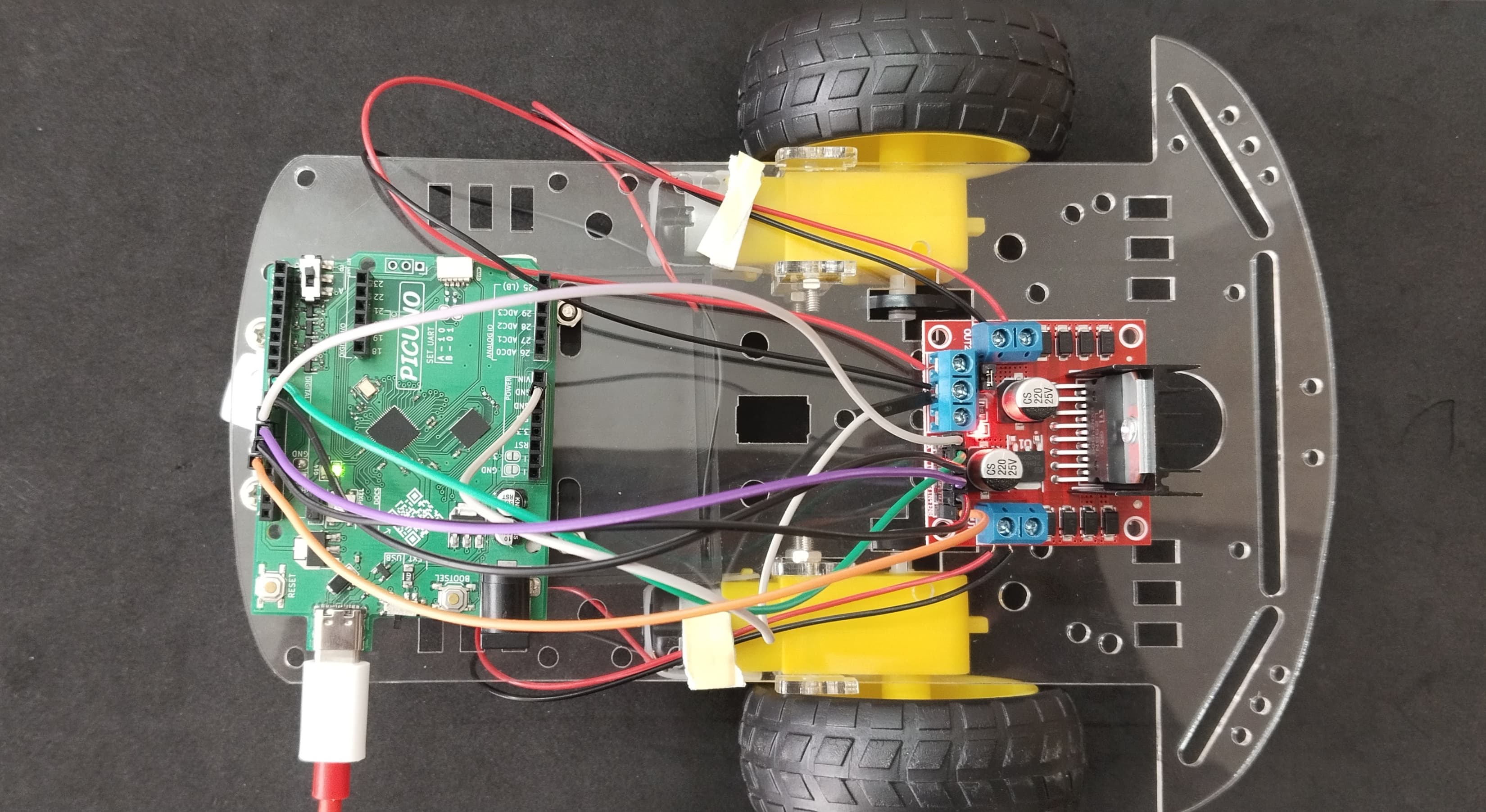
CIRCUIT DIAGRAM:

- OUT1 & OUT2: Connect these two screw terminals to the outputs for the first motor (e.g., the left wheel). Connect the two wires from one DC motor here.
- OUT3 & OUT4: Connect these two screw terminals to the outputs for the second motor (e.g., the right wheel). Connect the two wires from the other DC motor here.
- Connect the positive terminal (+) of the 4xAA battery pack to the 12V screw terminal.
- Connect the negative terminal (-) of the 4xAA battery pack to the GND screw terminal.
- Also connect the GND terminal on the L298N to a GND pin on the microcontroller to create a common ground.
- Connect the IN1 pin (Left motor) to GPIO 8.
- Connect the IN2 pin (Left motor) to GPIO 9.
- Connect the ENA pin (Left motor speed) to GPIO 10.
- Connect the IN1 pin (Right motor) to GPIO 11.
- Connect the IN2 pin (Right motor) to GPIO 12.
- Connect the ENB pin (Right motor speed) to GPIO 13.
NOTE: Remove the ENA and ENB jumpers on the L298N motor driver.
OPTIONAL: You can power the PICUNO using an external power supply (9V Battery) through DC Jack, once you have uploaded the code to the microcontroller.
SCHEMATIC:
L298N Motor Driver:
OUT2 & OUT2 → Outputs for the Left Motor.
OUT3 & OUT4 → Outputs for the Right Motor.
12V → positive terminal (+) of 4xAA battery pack.
GND → negative terminal (-) of 4xAA battery pack → GND on PICUNO.
IN1 (Left Motor) → GPIO 8
IN2 (Left Motor) → GPIO 9
ENA (Left Motor speed) → GPIO 10
IN3 (Right Motor) → GPIO 11
IN4 (Right Motor) → GPIO 12
ENB (Right Motor) → GPIO 13
CODE -- C:
// Left Motor (Motor A)
const int L_IN1_PIN = 8;
const int L_IN2_PIN = 9;
const int L_ENA_PIN = 10;
// Right Motor (Motor B)
const int R_IN3_PIN = 11;
const int R_IN4_PIN = 12;
const int R_ENB_PIN = 13;
void setup() {
pinMode(L_IN1_PIN, OUTPUT);
pinMode(L_IN2_PIN, OUTPUT);
pinMode(L_ENA_PIN, OUTPUT);
pinMode(R_IN3_PIN, OUTPUT);
pinMode(R_IN4_PIN, OUTPUT);
pinMode(R_ENB_PIN, OUTPUT);
Serial.begin(9600);
Serial.println("Starting infinite motor loop...");
}
void setMotorSpeed(char motor, int speed) {
// speed is from -100 to 100
int duty = map(abs(speed), 0, 100, 0, 255);
if (motor == 'L') {
if (speed > 0) { // Forward
digitalWrite(L_IN1_PIN, HIGH);
digitalWrite(L_IN2_PIN, LOW);
} else if (speed < 0) { // Backward
digitalWrite(L_IN1_PIN, LOW);
digitalWrite(L_IN2_PIN, HIGH);
} else { // Stop
digitalWrite(L_IN1_PIN, LOW);
digitalWrite(L_IN2_PIN, LOW);
}
analogWrite(L_ENA_PIN, duty);
}
else if (motor == 'R') {
if (speed > 0) { // Forward
digitalWrite(R_IN3_PIN, HIGH);
digitalWrite(R_IN4_PIN, LOW);
} else if (speed < 0) { // Backward
digitalWrite(R_IN3_PIN, LOW);
digitalWrite(R_IN4_PIN, HIGH);
} else { // Stop
digitalWrite(R_IN3_PIN, LOW);
digitalWrite(R_IN4_PIN, LOW);
}
analogWrite(R_ENB_PIN, duty);
}
}
void loop() {
// Go forward at 80% speed for 1 second
Serial.println("Moving forward...");
setMotorSpeed('L', 80);
setMotorSpeed('R', 80);
delay(1000);
// Stop for 1 second
Serial.println("Stopping.");
setMotorSpeed('L', 0);
setMotorSpeed('R', 0);
delay(1000);
// Go backward at 80% speed for 1 second
Serial.println("Moving backward...");
setMotorSpeed('L', -80);
setMotorSpeed('R', -80);
delay(1000);
// Stop for 1 second before repeating
Serial.println("Stopping.");
setMotorSpeed('L', 0);
setMotorSpeed('R', 0);
delay(1000);
}
pinMode() - Explicitly setting each pin as an OUTPUT.
setMotorSpeed() function - Using Arduino's digitalWrite() for direction and analogWrite() for speed.
analogWrite() - This is the command for sending a PWM signal. It uses a value from 0 (off) to 255 (100% speed). The map() function is used to convert the 0-100 speed percentage to this 0-255 range.
loop() - The loop() function in Arduino is naturally infinite, so placing the movement sequence here will cause it to repeat forever.
CODE -- PYTHON:
from machine import Pin, PWM
from time import sleep
# Left Motor (Motor A)
L_IN1_PIN = 8
L_IN2_PIN = 9
L_ENA_PIN = 10
# Right Motor (Motor B)
R_IN3_PIN = 11
R_IN4_PIN = 12
R_ENB_PIN = 13
# Left Motor
L_IN1 = Pin(L_IN1_PIN, Pin.OUT)
L_IN2 = Pin(L_IN2_PIN, Pin.OUT)
L_ENA = PWM(Pin(L_ENA_PIN))
L_ENA.freq(1000)
# Right Motor
R_IN3 = Pin(R_IN3_PIN, Pin.OUT)
R_IN4 = Pin(R_IN4_PIN, Pin.OUT)
R_ENB = PWM(Pin(R_ENB_PIN))
R_ENB.freq(1000)
# --- Helper Function ---
def set_motor_speed(motor, speed):
"""Sets motor speed. speed is from -100 to 100."""
duty = int(abs(speed) / 100 * 65535)
if motor == 'left':
if speed > 0: # Forward
L_IN1.high()
L_IN2.low()
elif speed < 0: # Backward
L_IN1.low()
L_IN2.high()
else: # Stop
L_IN1.low()
L_IN2.low()
L_ENA.duty_u16(duty)
elif motor == 'right':
if speed > 0: # Forward
R_IN3.high()
R_IN4.low()
elif speed < 0: # Backward
R_IN3.low()
R_IN4.high()
else: # Stop
R_IN3.low()
R_IN4.low()
R_ENB.duty_u16(duty)
print("Starting infinite motor loop...")
while True:
# Go forward at 80% speed for 2 seconds
print("Moving forward...")
set_motor_speed('left', 80)
set_motor_speed('right', 80)
sleep(1)
# Stop for 1 second
print("Stopping.")
set_motor_speed('left', 0)
set_motor_speed('right', 0)
sleep(1)
# Go backward at 80% speed for 2 seconds
print("Moving backward...")
set_motor_speed('left', -80)
set_motor_speed('right', -80)
sleep(1)
# Stop for 1 second before repeating
print("Stopping.")
set_motor_speed('left', 0)
set_motor_speed('right', 0)
sleep(1)
PWM(Pin(L_ENA_PIN)) - Creates a Pulse Width Modulation object for a speed control pin. PWM is how we control the speed of the DC motors.
set_motor_speed() function - This is the core logic. It takes a motor ('left' or 'right') and a speed (-100 to 100). It sets the direction pins (IN1/IN2) correctly for forward or reverse and then sets the speed using PWM.
duty_u16() - This function sets the PWM duty cycle, which controls the motor's speed. A value of 65535 is 100% speed.
while True: - This creates an infinite loop that causes the forward-stop-backward-stop sequence to repeat forever.