Automatic Party/Night Light
HARDWARE REQUIRED:
- PICUNO Microcontroller board
- 1 × HW-486 Photoresistor Module
- 1 × HW-481 7-Colour Flashing LED Module
- Jumper wires
- USB cable
DESCRIPTION:
This project creates a smart light that turns on automatically when the room gets dark. It uses a photoresistor to continuously measure the ambient light level. When the light level drops below a pre-defined threshold, the program sends a signal to activate the 7-color LED module, which begins its automatic flashing sequence. This is a fundamental concept in home automation and energy-saving systems.
CIRCUIT DIAGRAM:
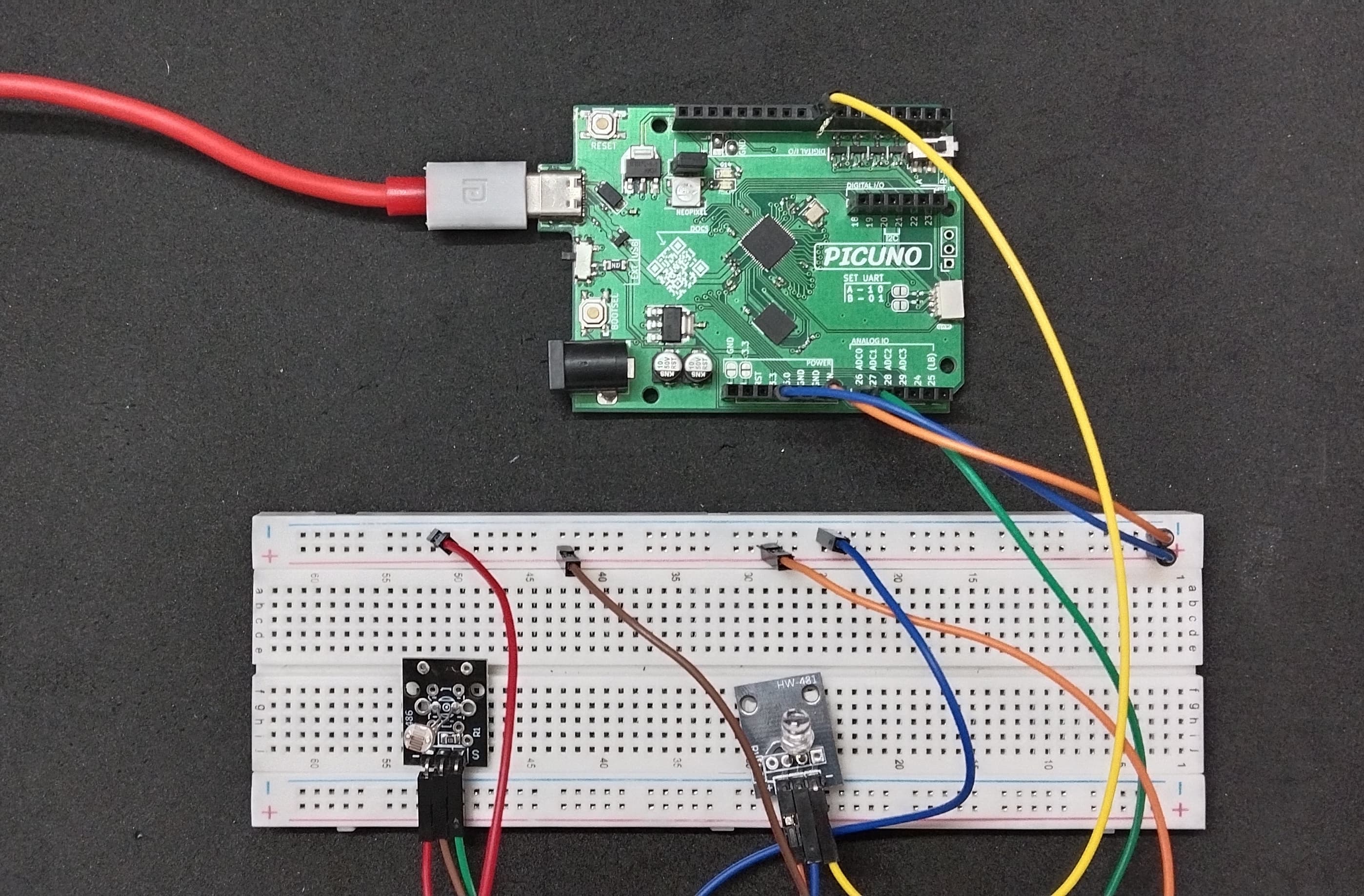
- Connect the VCC (+) pin to 5V.
- Connect the GND (-) pin to GND.
- Connect the Signal (S) pin to GPIO 8.
- Connect the GND (-) pin to GND pin.
- Connect the VCC (+) pin to 5V.
- Connect the Signal (S) pin to Analog Pin A0 (GPIO 26)
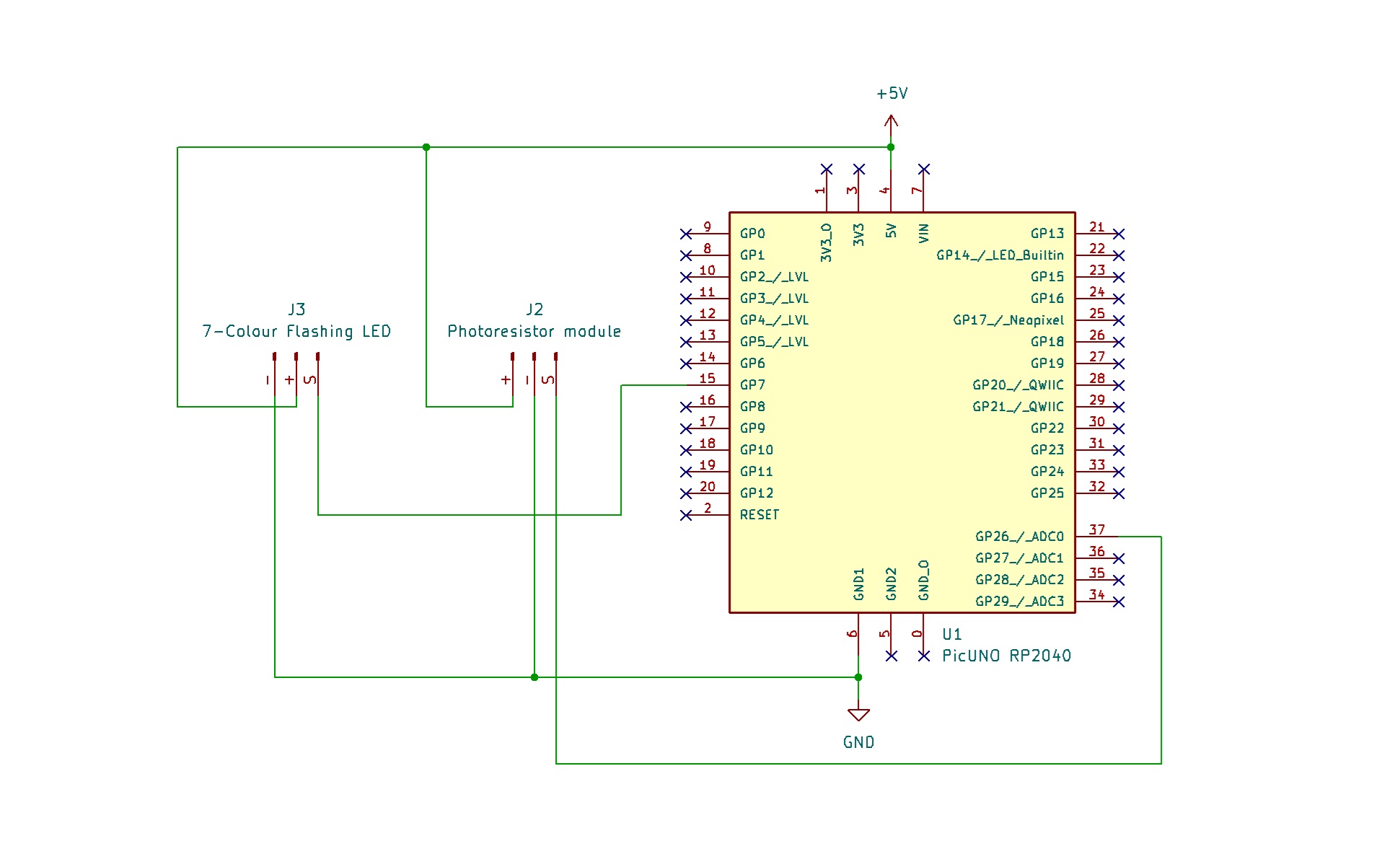
SCHEMATIC:
7-Colour Flashing LED Module:
VCC / (+) → 5V
GND / (-) → GND
Signal (S) → GPIO 8
Photoresistor Module:
VCC / (+) → 5V
GND / (-) → GND
Signal (S) → A0 (GPIO 26)
CODE -- C:
const int LDR_PIN = A0;
const int LED_PIN = 8;
const int LIGHT_THRESHOLD = 500;
void setup() {
// Initialize the pins
pinMode(LED_PIN, OUTPUT);
pinMode(LDR_PIN, INPUT);
Serial.begin(9600);
}
void loop() {
int lightValue = analogRead(LDR_PIN);
Serial.print("Current Light Level: ");
Serial.println(lightValue);
if (lightValue > LIGHT_THRESHOLD) {
digitalWrite(LED_PIN, HIGH);
} else {
digitalWrite(LED_PIN, LOW);
}
delay(200);
}
LIGHT_THRESHOLD - A constant variable that holds your trigger point. You should adjust this value based on the readings you see in the Serial Monitor for your room.
analogRead(LDR_PIN) - Reads the Analog voltage from the photoresistor module, which corresponds to the brightness of the light hitting it.
Serial.println(lightValue) - This is a key debugging tool. It prints the live light reading to your computer, allowing you to see the values for "bright" and "dark" in your room so you can choose a good threshold.
if (lightValue > LIGHT_THRESHOLD) - This is the core logic. It compares the current light level to your set threshold and turns the LED on or off accordingly.
CODE -- PYTHON:
from machine import Pin, ADC
from time import sleep
led = Pin(16, Pin.OUT)
ldr = ADC(Pin(26))
LIGHT_THRESHOLD = 30000
while True:
light_value = ldr.read_u16()
print(f"Current Light Level: {light_value}")
if light_value > LIGHT_THRESHOLD:
led.high()
else:
led.low()
sleep(0.2)
from time import sleep
led = Pin(16, Pin.OUT)
ldr = ADC(Pin(26))
LIGHT_THRESHOLD = 30000
while True:
light_value = ldr.read_u16()
print(f"Current Light Level: {light_value}")
if light_value > LIGHT_THRESHOLD:
led.high()
else:
led.low()
sleep(0.2)
LIGHT_THRESHOLD - A variable that holds the trigger point for darkness. Since the MicroPython ADC reads a much larger number (0-65535), this threshold is also larger.
ADC(Pin(26)) - Creates an Analog-to-Digital Converter object to read the voltage from the photoresistor.
ldr.read_u16() - Reads the Analog light level as a high-resolution 16-bit number.
print(f"...") - This is your most important tool for this project. Watch the numbers it prints as you cover and uncover the sensor to find the perfect LIGHT_THRESHOLD value for your room.
if light_value > LIGHT_THRESHOLD - The main logic that compares the live light reading to the calibrated threshold to decide whether to turn the LED on or off.