Autonomous Obstacle Avoiding Robot
HARDWARE REQUIRED:
- PICUNO Microcontroller board
- 1 × 4-Wheel Chassis (with wheels, 4 DC motors, etc.) full set
- 1 × 298N Motor Driver
- 1 × SG90 Servo Motor
- 1 × IR obstacle avoidance sensor
- 1 × 4xAA Battery pack (with fresh or rechargeable batteries)
- 1 × 9V Battery (optional for external power supply to PICUNO)
- Jumper wires
- USB cable
DESCRIPTION:
ASSEMBLY OF 4-WHEEL CHASIS KIT:
1.) Prepare the Chassis: If your chassis parts are acrylic, they often come with a protective paper or plastic film. Peel this film off all the pieces.
2.) Mount the Motors: Attach the four yellow DC motors to the lower chassis plate. Use the brackets and long screws/nuts that came with the kit to secure them firmly in place.
3.) Attach the Wheels: Push the four main wheels onto the plastic shafts of the motors. They should be a snug fit.
4.) Attach the Upper Chassis: Use the Screws/nuts to attach the upper chassis firmly. This will work as a holder for other components to be placed.
5.) Mount the Battery Holder: Use screws to attach the 4xAA battery pack at the top of the upper chassis.
6.) Mount the Electronics: Finally, mount the PICUNO, the L298N motor driver board and IR obstacle avoid sensor (placed on a servo motor's arm) onto the upper chassis, usually using screws/double tape. Position them such that to easily run wires to the motors.
CIRCUIT DIAGRAM:
- OUT1 & OUT2: Connect these two screw terminals to the outputs for the first motor and second motor (e.g., two wheels from left side). Connect the two wires (black) from both DC motors to OUT1 and other two wires (red) to OUT2.
- OUT3 & OUT4: Connect these two screw terminals to the outputs for the third and fourth motor (e.g., two wheels from right side). Connect the two wires (red) from both DC motors to OUT3 and other two wires (black) to OUT4.
- Connect the positive terminal (+) of the 4xAA battery pack to the 12V screw terminal.
- Connect the negative terminal (-) of the 4xAA battery pack to the GND screw terminal.
- Also connect the GND terminal on the L298N to a GND pin on the microcontroller to create a common ground.
- Connect the IN1 pin (Left side wheels) to GPIO 8.
- Connect the IN2 pin (Left side wheels) to GPIO 9.
- Connect the ENA pin (Left motors speed) to GPIO 10.
- Connect the IN1 pin (Right side wheels) to GPIO 11.
- Connect the IN2 pin (Right side wheels) to GPIO 12.
- Connect the ENB pin (Right motors speed) to GPIO 13.
NOTE: Remove the ENA and ENB jumpers on the L298N motor driver.
- Connect the Servo's VCC (Red) pin to the Positive (+) terminal of the 4xAA Battery Pack.
- Connect the Servo's GND (Brown) pin to GND.
- Connect the Servo's Signal (Yellow) pin to GPIO 15.
- Connect the Sensor's VCC (+) pin to 5V on board.
- Connect the Sensor's GND (-) pin to GND.
- Connect the Sensor's OUT pin to GPIO 16.
OPTIONAL: You can power the PICUNO using an external power supply (9V Battery) through DC Jack, once you have uploaded the code to the microcontroller.
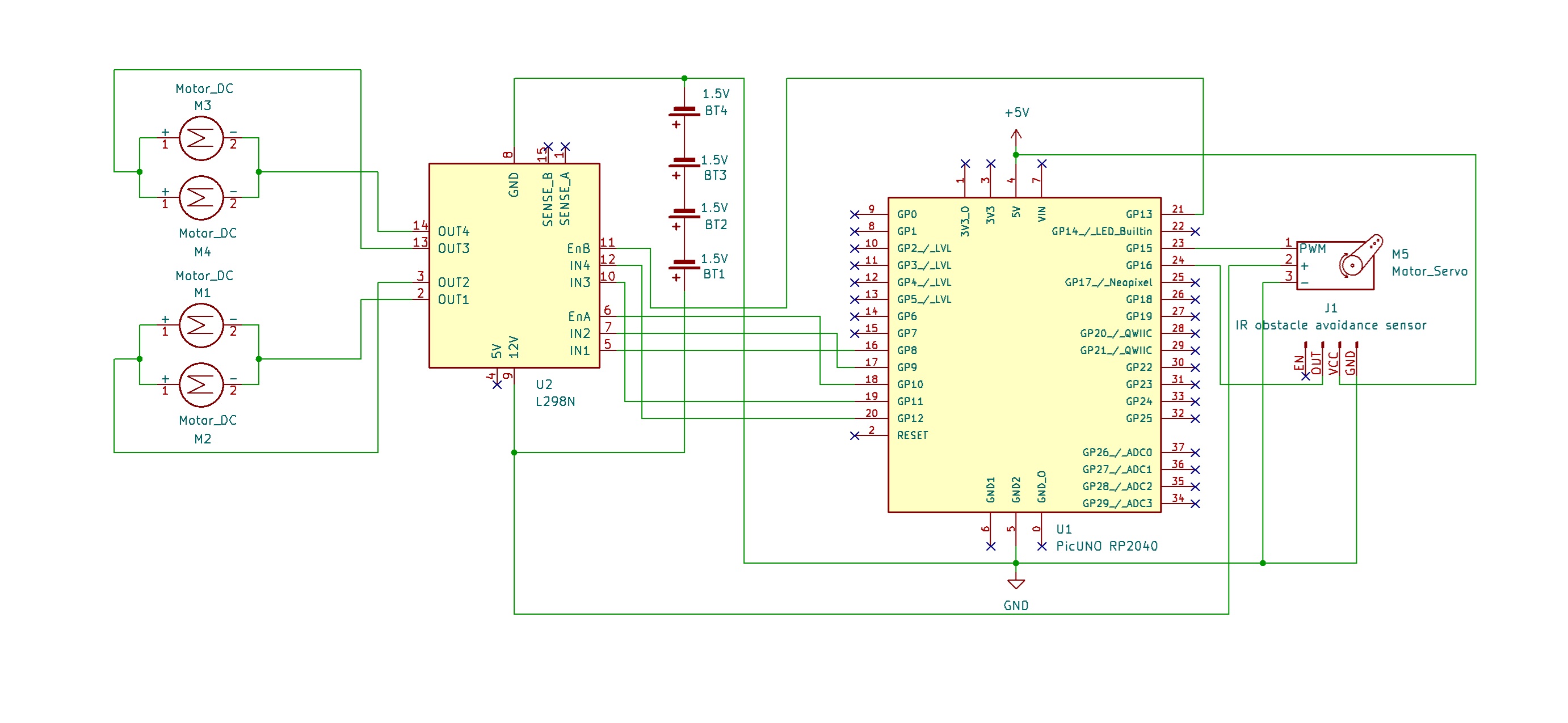
SCHEMATIC:
L298N Motor Driver:
OUT1 & OUT2 → Outputs for the Left side Motors.
OUT3 & OUT4 → Outputs for the Right side Motors.
12V → positive terminal (+) of 4xAA battery pack.
GND → negative terminal (-) of 4xAA battery pack → GND on PICUNO.
IN1 (Left side Motors) → GPIO 8
IN2 (Left side Motors) → GPIO 9
ENA (Left Motors speed) → GPIO 10
IN3 (Right side Motors) → GPIO 11
IN4 (Right side Motors) → GPIO 12
ENB (Right Motors speed) → GPIO 13
Servo Motor:
VCC (Red Wire) → 4xAA Battery Pack (+)
GND (Brown Wire) → GND
Signal (Yellow Wire) → GPIO 15
IR Obstacle Avoidance Sensor:
VCC / (+) → 5V
GND / (-) → GND
OUT → GPIO 16
CODE -- C:
1 2 3 4 5 6 7 8 9 10 11 12 13 14 15 16 17 18 19 20 21 22 23 24 25 26 27 28 29 30 31 32 33 34 35 36 37 38 39 40 41 42 43 44 45 46 47 48 49 50 51 52 53 54 55 56 57 58 59 60 61 62 63 64 65 66 67 68 69 70 71 72 73 74 75 76 77 78 79 80 81 82 83 84 85 86 87 88 89 90 91 92 #include <Servo.h> const int L_IN1=8, L_IN2=9, L_ENA=10; const int R_IN3=11, R_IN4=12, R_ENB=13; const int SERVO_PIN = 15; const int AVOID_SENSOR_PIN = 16; Servo myServo; // --- Motor Control Functions --- void setMotorSpeed(char motor, int speed) { int duty = map(abs(speed), 0, 100, 0, 255); if (motor == 'L') { if (speed > 0) { digitalWrite(L_IN1, HIGH); digitalWrite(L_IN2, LOW); } else if (speed < 0) { digitalWrite(L_IN1, LOW); digitalWrite(L_IN2, HIGH); } else { digitalWrite(L_IN1, LOW); digitalWrite(L_IN2, LOW); } analogWrite(L_ENA, duty); } else if (motor == 'R') { if (speed > 0) { digitalWrite(R_IN3, HIGH); digitalWrite(R_IN4, LOW); } else if (speed < 0) { digitalWrite(R_IN3, LOW); digitalWrite(R_IN4, HIGH); } else { digitalWrite(R_IN3, LOW); digitalWrite(R_IN4, LOW); } analogWrite(R_ENB, duty); } } void forward(int speed = 50) { setMotorSpeed('L', speed); setMotorSpeed('R', speed); } void backward(int speed = 50) { setMotorSpeed('L', -speed); setMotorSpeed('R', -speed); } void turn_left(int speed = 60) { setMotorSpeed('L', -speed); setMotorSpeed('R', speed); } void turn_right(int speed = 60) { setMotorSpeed('L', speed); setMotorSpeed('R', -speed); } void stopMotors() { setMotorSpeed('L', 0); setMotorSpeed('R', 0); } // --- Obstacle Avoidance Logic --- String lookAround() { Serial.println("Looking for a clear path..."); myServo.write(30); // Look right delay(500); bool rightIsClear = (digitalRead(AVOID_SENSOR_PIN) == HIGH); myServo.write(150); // Look left delay(700); bool leftIsClear = (digitalRead(AVOID_SENSOR_PIN) == HIGH); myServo.write(90); // Return to center delay(400); if (leftIsClear && !rightIsClear) { Serial.println("Path is clear to the left."); return "left"; } else if (rightIsClear && !leftIsClear) { Serial.println("Path is clear to the right."); return "right"; } else if (leftIsClear && rightIsClear) { Serial.println("Both paths clear, choosing left."); return "left"; } else { Serial.println("Both paths blocked, turning around."); return "blocked"; } } void setup() { pinMode(L_IN1, OUTPUT); pinMode(L_IN2, OUTPUT); pinMode(L_ENA, OUTPUT); pinMode(R_IN3, OUTPUT); pinMode(R_IN4, OUTPUT); pinMode(R_ENB, OUTPUT); pinMode(AVOID_SENSOR_PIN, INPUT); myServo.attach(SERVO_PIN); Serial.begin(9600); Serial.println("Starting Autonomous Robot..."); myServo.write(90); // Look straight ahead delay(1000); } void loop() { // The avoid sensor's pin is LOW when it detects an obstacle if (digitalRead(AVOID_SENSOR_PIN) == LOW) { Serial.println("Obstacle detected! Stopping."); stopMotors(); backward(40); delay(400); stopMotors(); String directionToTurn = lookAround(); if (directionToTurn == "left") { turn_left(); delay(600); // Adjust time for a good 90-degree turn stopMotors(); } else if (directionToTurn == "right") { turn_right(); delay(600); stopMotors(); } else { // Blocked turn_right(80); // Turn with more speed delay(1000); // Adjust time for a 180-degree turn stopMotors(); } } else { forward(60); // Path is clear, drive forward } delay(50); }
High-Level Movement Functions - Functions like forward(), backward(), and turn_left() make the main code easy to read. They act as simple commands that call the setMotorSpeed() function with the correct parameters for each wheel to achieve a specific movement.
myServo.write(angle) - This command from the Servo library tells the servo motor to move to a specific angle (e.g., 30 degrees to look right, 150 to look left).
lookAround() Function - This is the robot's "decision-making brain." It commands the servo to turn the AVOID_SENSOR_PIN to the right and left, reading the sensor at each position to see if the path is clear (HIGH) or blocked (LOW). Based on these readings, it returns a simple command: "left", "right", or "blocked".
Main loop() - This is the part of the code that runs forever. It continuously checks the AVOID_SENSOR_PIN using digitalRead(). If the path is clear, it calls forward(60) to drive ahead. If it detects an obstacle (digitalRead(...) == LOW), it stops, reverses briefly, and then calls the lookAround() function to decide which way to turn.
CODE -- PYTHON:
1 2 3 4 5 6 7 8 9 10 11 12 13 14 15 16 17 18 19 20 21 22 23 24 25 26 27 28 29 30 31 32 33 34 35 36 37 38 39 40 41 42 43 44 45 46 47 48 49 50 51 52 53 54 55 56 57 58 59 60 61 62 63 64 65 66 67 68 69 70 71 72 73 74 75 76 77 78 79 80 81 82 83 84 85 86 87 88 89 90 91 92 93 94 95 96 97 98 99 100 101 from machine import Pin, PWM from time import sleep_ms L_IN1 = Pin(8, Pin.OUT); L_IN2 = Pin(9, Pin.OUT); L_ENA = PWM(Pin(10)) R_IN3 = Pin(11, Pin.OUT); R_IN4 = Pin(12, Pin.OUT); R_ENB = PWM(Pin(13)) L_ENA.freq(1000); R_ENB.freq(1000) servo = PWM(Pin(15)) servo.freq(50) avoid_sensor = Pin(16, Pin.IN) # --- Motor Control Functions --- def set_motor_speed(motor, speed): duty = int(abs(speed) / 100 * 65535) if motor == 'left': if speed > 0: L_IN1.high(); L_IN2.low() elif speed < 0: L_IN1.low(); L_IN2.high() else: L_IN1.low(); L_IN2.low() L_ENA.duty_u16(duty) elif motor == 'right': if speed > 0: R_IN3.high(); R_IN4.low() elif speed < 0: R_IN3.low(); R_IN4.high() else: R_IN3.low(); R_IN4.low() R_ENB.duty_u16(duty) def forward(speed=50): set_motor_speed('left', speed); set_motor_speed('right', speed) def backward(speed=50): set_motor_speed('left', -speed); set_motor_speed('right', -speed) def turn_left(speed=60): set_motor_speed('left', -speed); set_motor_speed('right', speed) def turn_right(speed=60): set_motor_speed('left', speed); set_motor_speed('right', -speed) def stop(): set_motor_speed('left', 0); set_motor_speed('right', 0) # --- Servo Control Function --- def set_servo_angle(angle): duty = int(((angle / 180) * (8350 - 1350)) + 1350) servo.duty_u16(duty) # --- Obstacle Avoidance Logic --- def look_around(): """Looks left and right and returns which direction is clearer.""" print("Looking for a clear path...") set_servo_angle(30) sleep_ms(500) right_is_clear = avoid_sensor.value() == 1 # Look left (high angle) set_servo_angle(150) sleep_ms(700) left_is_clear = avoid_sensor.value() == 1 # Return to center set_servo_angle(90) sleep_ms(400) if left_is_clear and not right_is_clear: print("Path is clear to the left.") return 'left' elif right_is_clear and not left_is_clear: print("Path is clear to the right.") return 'right' elif left_is_clear and right_is_clear: print("Both paths clear, choosing left.") return 'left' # Default to left if both are clear else: print("Both paths blocked, turning around.") return 'blocked' # --- Main Program Loop --- print("Starting Autonomous Robot...") set_servo_angle(90) sleep_ms(1000) while True: if avoid_sensor.value() == 0: print("Obstacle detected! Stopping.") stop() backward(40) # Back up a little to give turning room sleep_ms(400) stop() direction_to_turn = look_around() if direction_to_turn == 'left': turn_left() sleep_ms(600) # 90-degree turn stop() elif direction_to_turn == 'right': turn_right() sleep_ms(600) # 90-degree turn stop() else: # Blocked, so turn around turn_right(80) # Turn with more speed sleep_ms(1000) # 180-degree turn stop() else: # Path is clear, so drive forward forward(60) sleep_ms(50)
High-Level Movement Functions - Functions like forward(), backward(), and turn_left() make the main code easy to read. They act as simple commands that call the set_motor_speed() function with the correct parameters for each wheel to achieve a specific movement.
set_servo_angle(angle) - This function takes a desired angle (e.g., 90 degrees) and converts it into the specific PWM signal (duty) that the servo motor needs to move to that exact position.
look_around() Function - This is the robot's "decision-making brain." It commands the servo to turn the avoid_sensor to the right and left, reading the sensor at each position to see if the path is clear. Based on these readings, it returns a simple command: 'left', 'right', or 'blocked'.
Main while Loop - This is the part of the code that runs forever. It continuously checks the avoid_sensor. If the path is clear, it calls forward(60) to drive ahead. If it detects an obstacle (if avoid_sensor.value() == 0:), it stops, reverses briefly, and then calls the look_around() function to decide which way to turn.