Joystick Controlled Pan And Tilt Servo Arm
HARDWARE REQUIRED:
- PICUNO Microcontroller board
- 2 × SG90 Servo Motor
- 1 × HW-504 Joystick Module
- 1 × 4xAA Battery Pack (for external power supply)
- Jumper wires
- USB cable
DESCRIPTION:
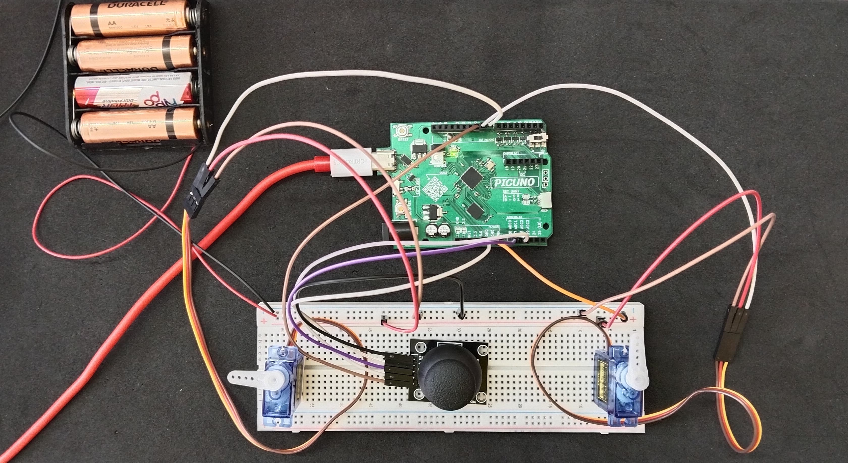
This project creates a 2-axis Pan and Tilt mechanism controlled in real-time by a joystick. Two servos work together to control the horizontal (pan) and vertical (tilt) movement. The joystick provides intuitive, two-dimensional Analog input, which is translated directly into servo positions. This project serves as a foundational building block for robotic camera gimbals, sensor turrets, or articulated arms.
CIRCUIT DIAGRAM:
- Connect the both Servo's VCC (Red) pin to the Positive (+) terminal of the 4xAA Battery Pack.
- Connect the both Servo's GND (Brown) pin to GND.
- Connect the Pan Servo's Signal (Yellow) pin to GPIO 8.
- Connect the Tilt Servo's Signal (Yellow) pin to GPIO 9.
- JOYSTICK MODULE:
- Connect the VCC pin to 5V pin on the board.
- Connect the GND pin to GND pin on board.
- Connect the VRx pin to Analog Pin A0 (GPIO 26).
- Connect the VRy pin to Analog Pin A1 (GPIO 27).
- Connect the Negative (-) terminal of the 4xAA Battery Pack to GND pin on the PICUNO board to create a common ground connection.
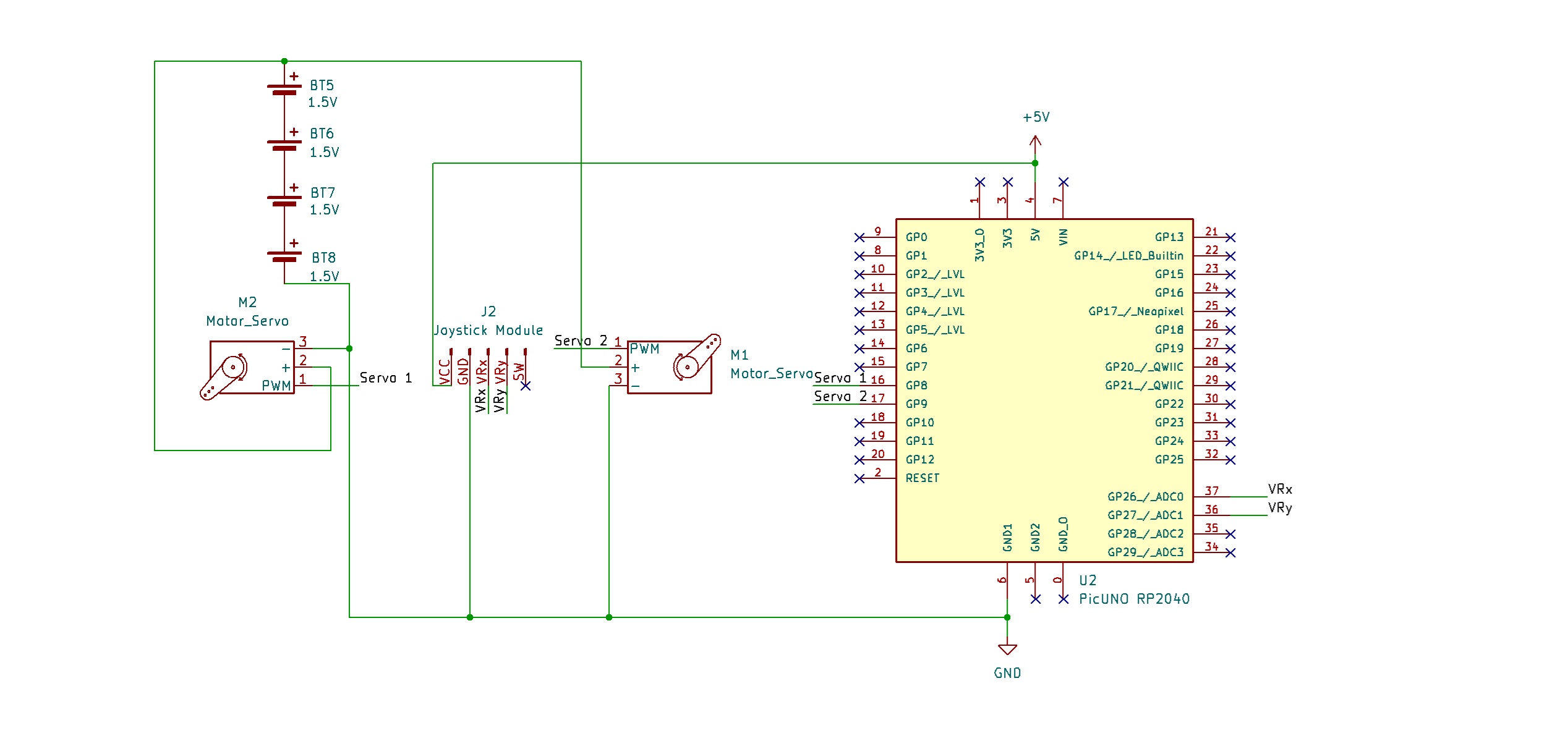
SCHEMATIC:
Pan Servo Motor:
VCC (Red Wire) → 4xAA Battery Pack (+)
GND (Brown Wire) → GND
Signal (Yellow Wire) → GPIO 8
Tilt Servo Motor:
VCC (Red Wire) → 4xAA Battery Pack (+)
GND (Brown Wire) → GND
Signal (Yellow Wire) → GPIO 9
Joystick Module:
VCC → 5V
GND → GND
VRx → A0
VRy → A1
Common Ground Connection:
4xAA Battery Pack (-) → PICUNO Board GND
CODE -- C:
#include <Servo.h>
#define JOY_X_PIN A0
#define JOY_Y_PIN A1
#define PAN_SERVO_PIN 8
#define TILT_SERVO_PIN 9
Servo panServo;
Servo tiltServo;
void setup() {
Serial.begin(9600);
Serial.println("Pan/Tilt Ready");
panServo.attach(PAN_SERVO_PIN, 500, 2500);
tiltServo.attach(TILT_SERVO_PIN, 500, 2500);
panServo.write(90);
tiltServo.write(90);
delay(1000);
}
void loop() {
int joyX = analogRead(JOY_X_PIN);
int joyY = analogRead(JOY_Y_PIN);
int panAngle = map(joyX, 0, 1023, 0, 180);
int tiltAngle = map(joyY, 0, 1023, 180, 0); // Invert tilt axis for intuitive control
// Write angles to servos
panServo.write(panAngle);
tiltServo.write(tiltAngle);
// Display information on the Serial Monitor
Serial.print("Pan: ");
Serial.print(panAngle);
Serial.print(" Tilt: ");
Serial.println(tiltAngle);
delay(30);
}
analogRead(PIN) - This reads the voltage from an Analog pin (connected to the joystick) and converts it into a number between 0 and 1023.
panServo.write(angle) - This is the final command that tells the servo motor to move to the position specified by the angle variable.
panServo.attach(..., 500, 2500) - Both servos are attached using the custom pulse width range to ensure they can achieve their full 180-degree motion.
map() - Scales the joystick's 0-1023 input range to the servo's 0-180 degree output range.
CODE -- PYTHON:
from machine import Pin, ADC, PWM
from time import sleep
joy_x_adc = ADC(Pin(26)) # A0
joy_y_adc = ADC(Pin(27)) # A1
pan_pwm = PWM(Pin(8))
tilt_pwm = PWM(Pin(9))
pan_pwm.freq(50)
tilt_pwm.freq(50)
def map_value(x, in_min, in_max, out_min, out_max):
return (x - in_min) * (out_max - out_min) // (in_max - in_min) + out_min
def set_servo_angle(pwm_obj, angle):
angle = max(0, min(180, angle)) # Constrain angle
duty = map_value(angle, 0, 180, 1350, 8350)
pwm_obj.duty_u16(duty)
print("Pan/Tilt Ready")
set_servo_angle(pan_pwm, 90)
set_servo_angle(tilt_pwm, 90)
sleep(1)
# --- Main Loop ---
while True:
joy_x = joy_x_adc.read_u16()
joy_y = joy_y_adc.read_u16()
pan_angle = map_value(joy_x, 0, 65535, 0, 180)
tilt_angle = map_value(joy_y, 0, 65535, 180, 0) # Inverted for intuitive control
# Set servo positions
set_servo_angle(pan_pwm, pan_angle)
set_servo_angle(tilt_pwm, tilt_angle)
print(f"Pan: {pan_angle}, Tilt: {tilt_angle}")
sleep(0.03)
ADC and PWM Objects - These are created to handle Analog input from the joystick and generate the specific PWM signal required by the servos.
set_servo_angle() - A helper function used to handle the logic for setting a servo's angle, which makes the main code cleaner.
read_u16() - Reads the joystick's position as a high-resolution number from 0 to 65535.
print(f"...") - Uses an f-string to easily format and send the live angle data to your Thonny IDE's Shell for feedback.