Shock And Vibration Detector
HARDWARE REQUIRED:
- PICUNO Microcontroller board
- 1 × HW-513 Shock sensor module
- 1 × HW-480 Two-colour LED Module
- 2 × 220Ω resistors (for current-limiting)
- Jumper wires
- USB cable
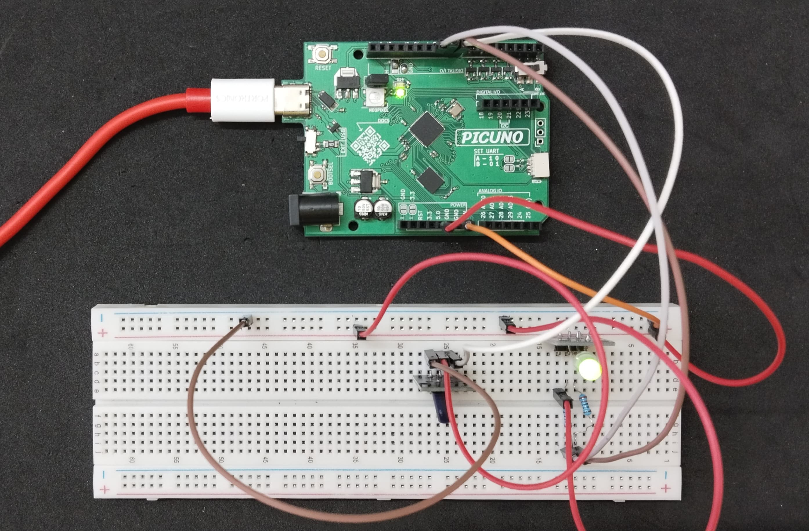
DESCRIPTION:
The Shock sensor module contains a very small percussive spring mechanism that is sensitive to sudden movements. When the module is shaken, the conductive spring within the sensor will move, resulting in a HIGH (1) signal being sent to the Arduino, and the LED module will switch to a red colour. When no vibration is detected, the sensor module will send back a LOW (0) signal, resulting in the LED module displaying a green colour (its default state).
CIRCUIT DIAGRAM:
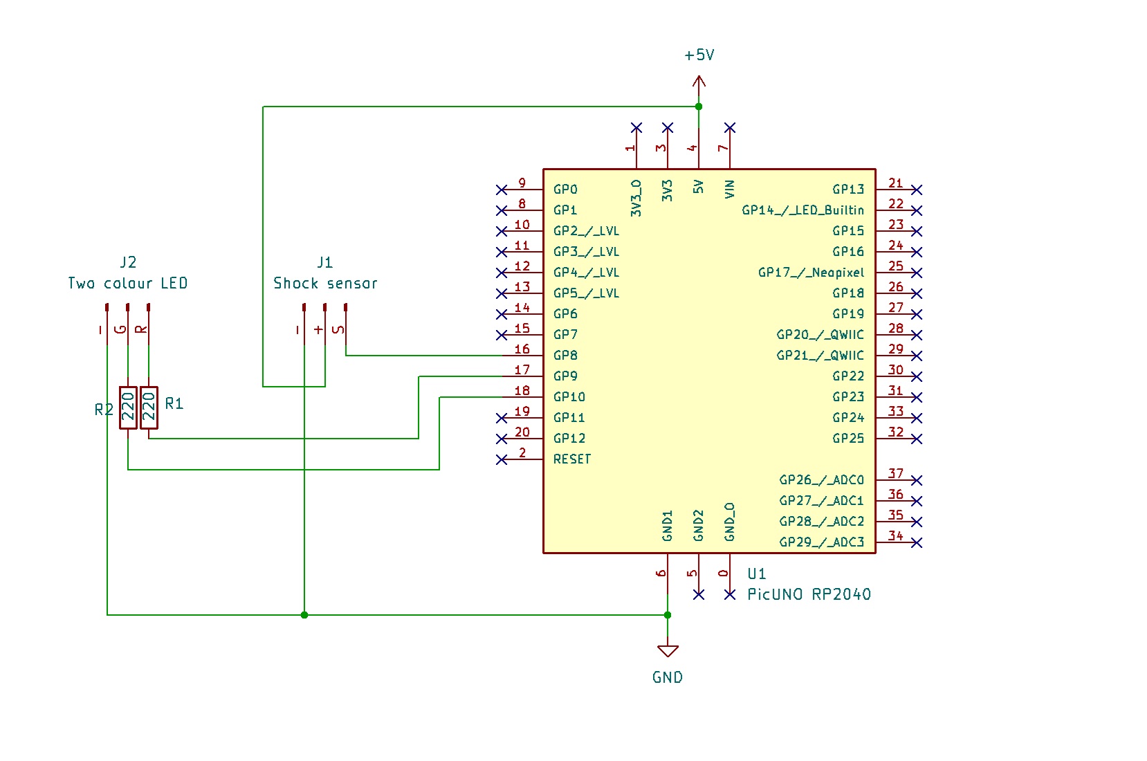
- Connect the Shock sensor's VCC (+) pin to 5V.
- Connect the Shock sensor's GND (-) pin to GND.
- Connect the Shock sensor's Signal (S) pin to GPIO 8.
- Two-Colour LED Module:
- Connect the GND (-) pin to GND pin on board.
- Connect the Red LED (R) pin to one end of 220Ω resistor and the other end of resistor to GPIO 9.
- Connect the Green LED (G) pin to one end of 220Ω resistor and the other end of resistor to GPIO 10.
SCHEMATIC:
Shock Sensor Module:
VCC / (+) → 5V
GND / (-) → GND
Signal (S) → GPIO 8
Two-Colour LED Module:
GND / (-) → GND
Red LED Pin (R) → GPIO 9
Green LED (G) Pin → GPIO 10
CODE -- C:
const int SHOCK_SENSOR_PIN = 8;
const int RED_LED_PIN = 9;
const int GREEN_LED_PIN = 10;
int lastShockState = LOW;
void setup() {
pinMode(SHOCK_SENSOR_PIN, INPUT);
pinMode(GREEN_LED_PIN, OUTPUT);
pinMode(RED_LED_PIN, OUTPUT);
digitalWrite(GREEN_LED_PIN, HIGH);
digitalWrite(RED_LED_PIN, LOW);
Serial.begin(9600);
Serial.println("Shock Detector Armed. System Stable.");
}
void loop() {
int currentShockState = digitalRead(SHOCK_SENSOR_PIN);
if (currentShockState != lastShockState) {
if (currentShockState == HIGH) {
// SHOCK DETECTED
digitalWrite(GREEN_LED_PIN, LOW);
digitalWrite(RED_LED_PIN, HIGH);
Serial.println("VIBRATION DETECTED!");
} else {
// NO SHOCK
digitalWrite(GREEN_LED_PIN, HIGH);
digitalWrite(RED_LED_PIN, LOW);
Serial.println("System Stable.");
}
// Update the last state
lastShockState = currentShockState;
}
delay(50);
}
pinMode() - Configures the microcontroller's pins. INPUT for the sensor to receive data, and OUTPUT for the LEDs to send data.
digitalRead() - Reads the digital signal (either HIGH or LOW) from the shock sensor's D0 pin.
digitalWrite() - Sends a HIGH (on) or LOW (off) signal to a pin, which turns the corresponding LED color on or off.
if (currentShockState != lastShockState) - This logic makes the code more efficient, as it only changes the LEDs and prints a message when the sensor's state actually flips, rather than every single time the loop runs.
CODE -- PYTHON:
from machine import Pin
import time
shock_sensor = Pin(8, Pin.IN)
red_led = Pin(9, Pin.OUT)
green_led = Pin(10, Pin.OUT)
last_state = 0
green_led.high() # Turn green on
red_led.low() # Turn red off
print("Shock Detector Armed. System Stable.")
while True:
current_state = shock_sensor.value()
if current_state != last_state:
if current_state == 1:
# SHOCK DETECTED
green_led.low()
red_led.high()
print("VIBRATION DETECTED!")
else:
# NO SHOCK
green_led.high()
red_led.low()
print("System Stable.")
last_state = current_state
time.sleep_ms(50)
Pin(8, Pin.IN) - Creates a Pin object for the sensor, configured as a digital input.
Pin(9, Pin.OUT) - Creates Pin objects for the LEDs, configured as digital outputs.
shock_sensor.value() - Reads the current digital value from the sensor pin, returning 1 for HIGH or 0 for LOW.
.high() / .low() - A simple way to turn a Pin object on (HIGH) or off (LOW).
Pin(9, Pin.OUT) - Creates Pin objects for the LEDs, configured as digital outputs.
shock_sensor.value() - Reads the current digital value from the sensor pin, returning 1 for HIGH or 0 for LOW.
.high() / .low() - A simple way to turn a Pin object on (HIGH) or off (LOW).