Heartbeat Monitoring System With LCD Display

HARDWARE REQUIRED:
- PICUNO Microcontroller board
- 1 × 16x2 I2C LCD Display
- 1 × KY-039 Heartbeat Sensor
- 1 × Buzzer
- Jumper wires
- USB cable
- 9V Battery with a snap connector (to power the board via the DC Jack)
DESCRIPTION:
This project creates a functional Heartbeat Monitor that measures a user's pulse in Beats Per Minute (BPM). An Analog pulse sensor detects the user's heartbeat, typically from a fingertip. The PICUNO counts the number of beats over a 10-second period, calculates the BPM, and displays this value on an I2C LCD. For safety, the system also acts as an alarm: if the measured BPM falls outside a predefined safe range (e.g., below 60 or above 120 BPM), an audible buzzer will sound.
LIBRARIES REQUIRED:
For C / Arduino IDE:
- Wire.h: Manages I2C communication (usually included by default).
- LiquidCrystal_I2C.h: The driver library for the I2C LCD module.
- i2c_lcd.py: The custom library file saved to the PICUNO board.
- The code also uses the built-in machine and time modules.
CIRCUIT DIAGRAM:
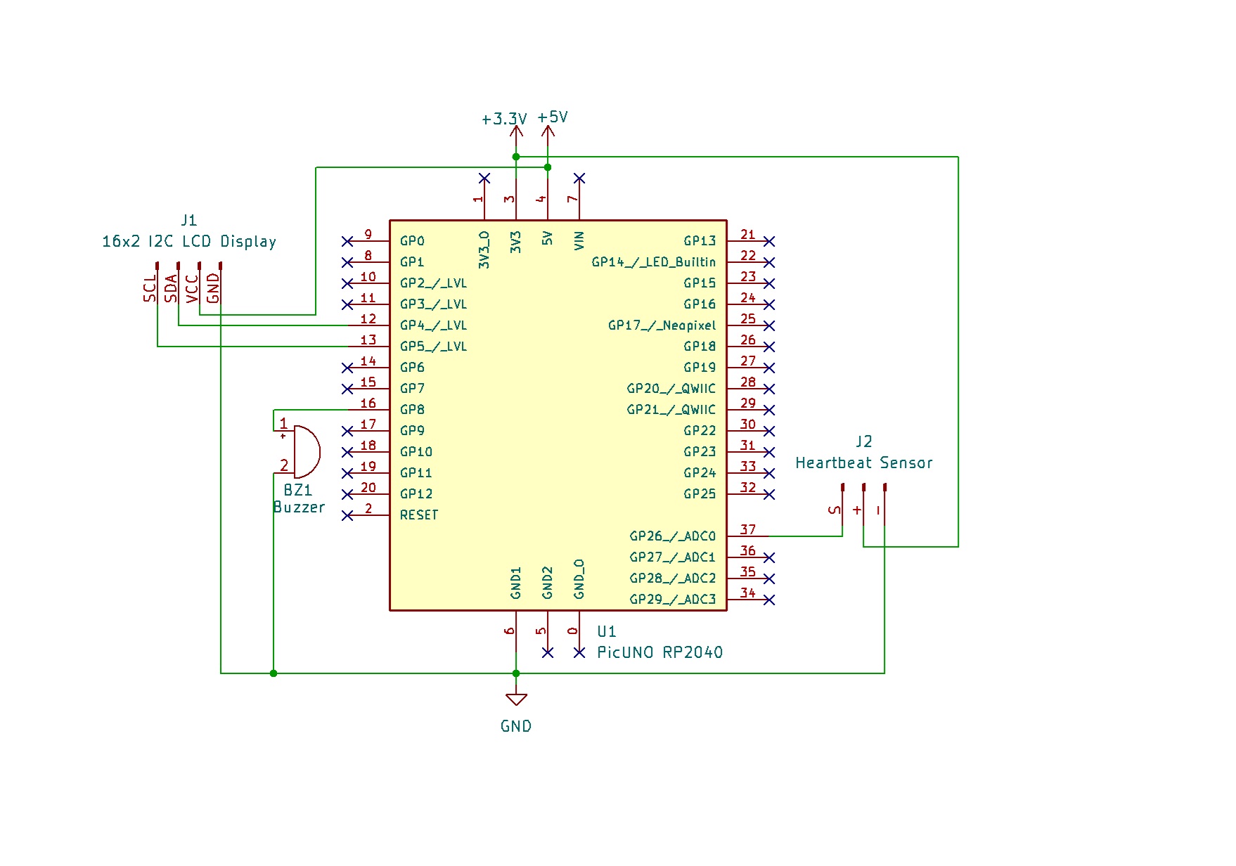
- Connect the positive terminal of the Buzzer to GPIO 8.
- Connect the negative terminal of the Buzzer to GND.
- HEARTBEAT/PULSE SENSOR MODULE
- Connect the - to GND.
- Connect the + to 3.3V.
- Connect the S to Analog Pin A0.
- I2C LCD DISPLAY:
- Connect the LCD Module's GND pin to a GND pin on board.
- Connect the LCD Module's VCC pin to the 5V pin on board.
- Connect the LCD Module's SDA pin GPIO 4 (SDA Pin on PICUNO).
- Connect the LCD Module's SCL pin GPIO 5 (SCL Pin on PICUNO).
SCHEMATIC:
Buzzer +ve terminal → GPIO 8
Buzzer -ve terminal → GND
HEARTBEAT/PULSE SENSOR:
+ → 3.3V
- → GND
S → A0
LCD Circuit:
LCD VCC → 5V
LCD GND → GND
LCD SDA → GPIO 4 (Board SDA Pin)
LCD SCL → GPIO 5 (Board SCL Pin)
CODE -- C:
#include <Wire.h>
#include <LiquidCrystal_I2C.h>
// Pin setup
const int PULSE_PIN = A0;
const int BUZZER_PIN = 8;
// I2C LCD setup
LiquidCrystal_I2C lcd(0x27, 16, 2);
// Constants
const int THRESHOLD = 550; // ADC threshold for peaks (needs tuning)
const int SAFE_MIN = 60;
const int SAFE_MAX = 120;
void setup() {
pinMode(BUZZER_PIN, OUTPUT);
lcd.init();
lcd.backlight();
lcd.print("Heartbeat Monitor");
}
int getBPM() {
int beatCount = 0;
unsigned long startTime = millis();
int duration = 10; // seconds
int previous = 0;
while ((millis() - startTime) < (duration * 1000)) {
int reading = analogRead(PULSE_PIN);
if (reading > THRESHOLD && previous <= THRESHOLD) {
beatCount++;
}
previous = reading;
delay(10);
}
int bpm = (beatCount * 60) / duration;
return bpm;
}
void loop() {
lcd.setCursor(0, 1);
lcd.print("Checking BPM... ");
int bpm = getBPM();
lcd.setCursor(0, 1);
lcd.print("BPM: ");
lcd.print(bpm);
lcd.print(" "); // Clear rest of line
if (bpm < SAFE_MIN || bpm > SAFE_MAX) {
digitalWrite(BUZZER_PIN, HIGH);
} else {
digitalWrite(BUZZER_PIN, LOW);
}
delay(2000);
}
THRESHOLD - This value is critical. It's the ADC reading that the signal must cross to count as a heartbeat. You will need to adjust this value based on your specific sensor.
getBPM() - This function counts beats for 10 seconds and calculates the final BPM.
if (reading > THRESHOLD && previous <= THRESHOLD) - This is "rising edge detection." It ensures that we only count each beat once as the signal rises past our threshold, not multiple times while it stays high.
(beatCount * 60) / duration - This formula scales the number of beats counted in 10 seconds to find the equivalent number of beats in 60 seconds (BPM).
CODE -- PYTHON:
from machine import ADC, Pin, I2C
from time import sleep, ticks_ms, ticks_diff
from i2c_lcd import I2cLcd
pulse_pin = ADC(Pin(26))
buzzer = Pin(8, Pin.OUT)
i2c = I2C(0, scl=Pin(5), sda=Pin(4), freq=400000)
lcd = I2cLcd(i2c, 0x27, 2, 16)
THRESHOLD = 25000 # ADC threshold for detecting peaks (tune as needed)
SAFE_MIN = 60
SAFE_MAX = 120
# Init
lcd.clear()
lcd.putstr("Heartbeat Monitor")
# Function to detect BPM
def get_bpm(duration=10):
beat_count = 0
start_time = ticks_ms()
previous = 0
while ticks_diff(ticks_ms(), start_time) < duration * 1000:
reading = pulse_pin.read_u16()
if reading > THRESHOLD and previous <= THRESHOLD:
beat_count += 1
previous = reading
sleep(0.01)
bpm = int((beat_count * 60) / duration)
return bpm
# Main Loop
while True:
lcd.move_to(0, 1)
lcd.putstr("Checking BPM... ")
bpm = get_bpm()
print("BPM:", bpm)
lcd.move_to(0, 1)
lcd.putstr("BPM: {:3d} ".format(bpm))
if bpm < SAFE_MIN or bpm > SAFE_MAX:
buzzer.value(1)
else:
buzzer.value(0)
sleep(2)
THRESHOLD - This is the value the 16-bit ADC reading must cross to count as a beat. You must tune this by first printing the raw sensor values to find a good trigger point.
get_bpm() - A dedicated function to measure the BPM. It counts beats over a 10-second duration.
ticks_ms() and ticks_diff() - These are used for accurate, non-blocking timekeeping to control the measurement duration.
if reading > THRESHOLD and previous <= THRESHOLD - This logic detects only the "rising edge" of a pulse, ensuring each heartbeat is counted only once.
(beat_count * 60) / duration - This formula extrapolates the number of beats counted during the sample window to calculate the beats per minute.