LDR-Controlled RGB Mood Lamp With LCD Display
HARDWARE REQUIRED:
- PICUNO Microcontroller board
- 1 × 16x2 I2C LCD Display
- 1 × Common Cathode RGB LED
- 1 × LDR (Light Dependent Resistor)
- 1 × 10kΩ resistor
- Jumper wires
- USB cable
- 9V Battery with a snap connector (to power the board via the DC Jack)
DESCRIPTION:
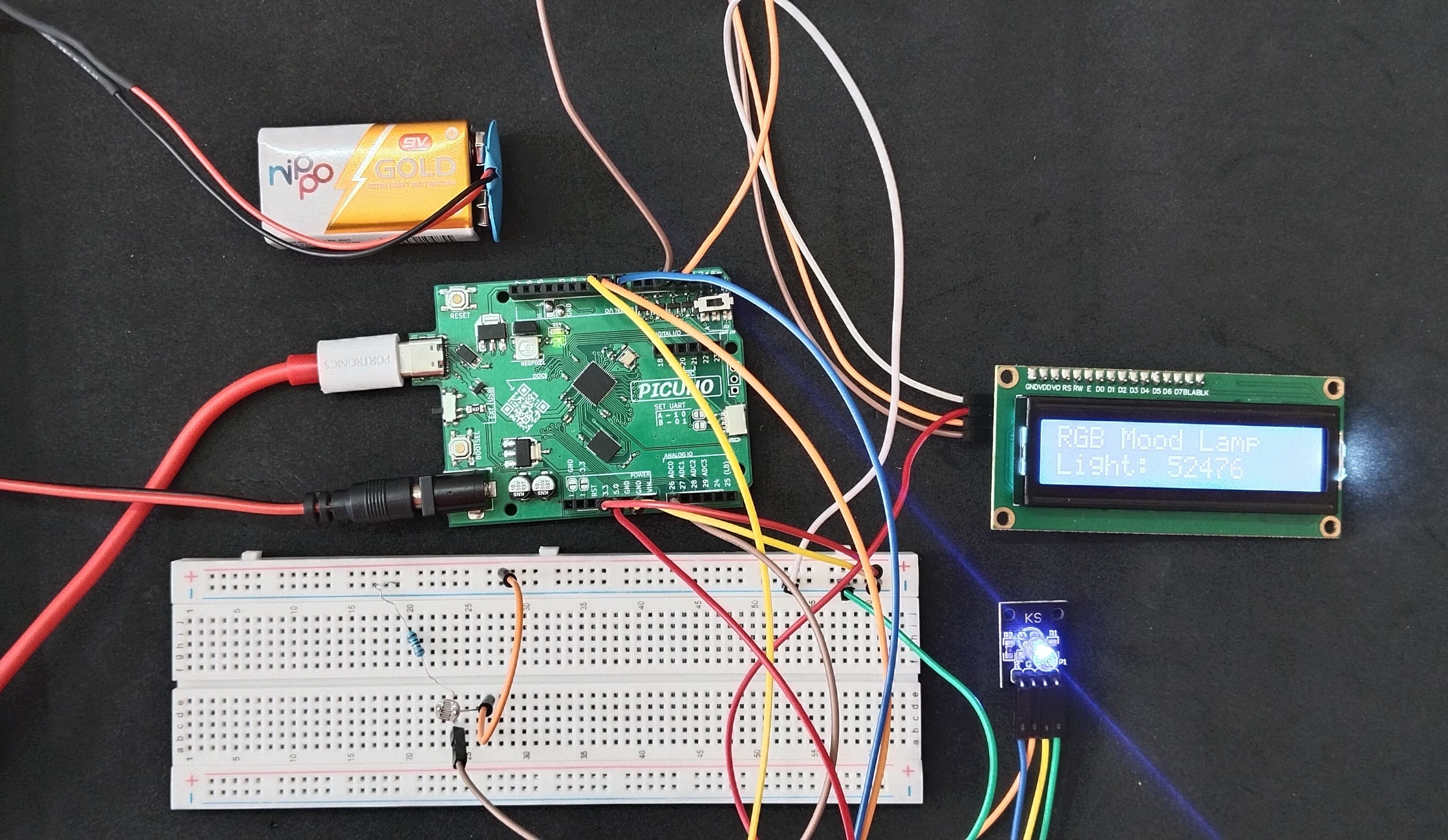
This project creates an ambient "Mood Lamp" that changes its colour based on the room's brightness. A Light Dependent Resistor (LDR) continuously measures the light level. The PICUNO reads this value and uses a set of thresholds to choose a colour for an RGB LED—for example, turning red in the dark and blue in bright light. The current raw light value from the LDR is also displayed in real-time on a 16x2 LCD screen, providing a complete, interactive feedback system.
LIBRARIES REQUIRED:
For C / Arduino IDE:
- Wire.h: Manages I2C communication (usually included by default).
- LiquidCrystal_I2C.h: The driver library for the I2C LCD module.
- i2c_lcd.py: The custom library file saved to the PICUNO board.
- The code also uses the built-in machine and time modules.
CIRCUIT DIAGRAM:

- Connect one leg of the LDR to 3.3V.
- Connect the other leg of the LDR to Analog Pin A0 (GPIO 26).
- Connect the 10kΩ resistor from A0 (GPIO 26) to GND.
- RGB LED COMMON CATHODE:
- Connect the cathode to GND.
- Connect the RED leg to GPIO 8.
- Connect the GREEN leg to GPIO 9.
- Connect the BLUE leg to GPIO 10.
- I2C LCD DISPLAY:
- Connect the LCD Module's GND pin to a GND pin on board.
- Connect the LCD Module's VCC pin to the 5V pin on board.
- Connect the LCD Module's SDA pin GPIO 4 (SDA Pin on PICUNO).
- Connect the LCD Module's SCL pin GPIO 5 (SCL Pin on PICUNO).
SCHEMATIC:
LDR one leg → 3.3V
LDR other leg → A0
A0 → 10kΩ Resistor → GND
RGB LED Circuit:
GPIO 8 → Red LED Pin
GPIO 9 → Green LED Pin
GPIO 10 → Blue LED Pin
Common Cathode Pin → GND
LCD Circuit:
LCD VCC → 5V
LCD GND → GND
LCD SDA → GPIO 4 (Board SDA Pin)
LCD SCL → GPIO 5 (Board SCL Pin)
CODE -- C:
#include <Wire.h>
#include <LiquidCrystal_I2C.h>
// Pin setup
const int ldrPin = A0; // LDR connected to ADC0
const int redPin = 8;
const int greenPin = 9;
const int bluePin = 10;
// I2C LCD setup
LiquidCrystal_I2C lcd(0x27, 16, 2);
// Function to set RGB color
void setColor(int r, int g, int b) {
digitalWrite(redPin, r);
digitalWrite(greenPin, g);
digitalWrite(bluePin, b);
}
void setup() {
// Set pin modes
pinMode(redPin, OUTPUT);
pinMode(greenPin, OUTPUT);
pinMode(bluePin, OUTPUT);
// Initialize LCD
lcd.init();
lcd.backlight();
lcd.clear();
lcd.print("RGB Mood Lamp");
}
void loop() {
int lightValue = analogRead(ldrPin);
// Display on LCD
lcd.setCursor(0, 1);
lcd.print("Light: ");
lcd.print(lightValue);
lcd.print(" "); // Add spaces to clear old characters
// RGB Logic - Note: Arduino ADC is 0-1023
if (lightValue < 200) { // Dark (LDR has high resistance, so voltage is low)
setColor(HIGH, LOW, LOW); // Red
} else if (lightValue < 500) {
setColor(HIGH, HIGH, LOW); // Yellow
} else if (lightValue < 750) {
setColor(HIGH, LOW, HIGH); // Purple
} else { // Bright
setColor(LOW, LOW, HIGH); // Blue
}
delay(500);
}
analogRead(ldrPin) - Reads the light level from the LDR circuit as a value from 0-1023.
setColor() - A helper function to easily turn the red, green, and blue LEDs on or off.
if/else if/else - This block checks the lightValue against different thresholds to determine which colour to display. The threshold values (200, 500, 750) may need to be adjusted for your specific room lighting.
setColor() - A helper function to easily turn the red, green, and blue LEDs on or off.
if/else if/else - This block checks the lightValue against different thresholds to determine which colour to display. The threshold values (200, 500, 750) may need to be adjusted for your specific room lighting.
CODE -- PYTHON:
from machine import Pin, ADC, I2C
from time import sleep
from i2c_lcd import I2cLcd
# Pin setup
ldr = ADC(Pin(26)) # LDR connected to ADC0
red = Pin(8, Pin.OUT)
green = Pin(9, Pin.OUT)
blue = Pin(10, Pin.OUT)
i2c = I2C(0, scl=Pin(5), sda=Pin(4), freq=400000)
lcd = I2cLcd(i2c, 0x27, 2, 16)
def set_color(r, g, b):
red.value(r)
green.value(g)
blue.value(b)
lcd.clear()
lcd.putstr("RGB Mood Lamp")
while True:
light_value = ldr.read_u16()
print("Light Value:", light_value)
# Display on LCD
lcd.move_to(0, 1)
lcd.putstr("Light: {:5d} ".format(light_value))
# RGB Logic
if light_value > 50000:
set_color(0, 0, 1) # Bright → Blue
elif light_value > 30000:
set_color(1, 0, 1) # Medium → Purple
elif light_value > 15000:
set_color(1, 1, 0) # Dim → Yellow
else:
set_color(1, 0, 0) # Dark → Red
sleep(0.5)
ldr.read_u16() - Reads the light level as a 16-bit value (0-65535). For an LDR wired this way, a low value means dark, and a high value means bright.
lcd.putstr("Light: {:5d} ".format(light_value)) - This formats the integer light_value to take up 5 spaces, ensuring that when the number changes (e.g., from 10000 to 9000), the old digits are overwritten with blank spaces.
if/elif/else - This logic block checks the light value against different thresholds and calls the set_color function to light up the appropriate combination of LEDs.