Line Following Robot
HARDWARE REQUIRED:
- PICUNO Microcontroller board
- 1 × 4-Wheel Chassis (with wheels, 4 DC motors, etc.) full set
- 1 × 298N Motor Driver
- 1 × Line Tracking sensor
- 1 × 4xAA Battery pack (with fresh or rechargeable batteries)
- 1 × 9V Battery (optional for external power supply to PICUNO)
- Jumper wires
- USB cable
DESCRIPTION:
This project turns your 4-wheel chassis into an autonomous robot that can follow the edge of a black line on a white surface. The robot uses a single infrared (IR) tracking sensor mounted underneath to detect the line. The program's logic is a simple but effective "zig-zag" algorithm: if the sensor sees white, it turns toward the line; if it sees black, it turns away from the line. This continuous, rapid correction keeps the robot centred on the edge of the path, allowing it to navigate a track you design.
ASSEMBLY OF 4-WHEEL CHASIS KIT:
1.) Prepare the Chassis: If your chassis parts are acrylic, they often come with a protective paper or plastic film. Peel this film off all the pieces.
2.) Mount the Motors: Attach the four yellow DC motors to the lower chassis plate. Use the brackets and long screws/nuts that came with the kit to secure them firmly in place.
3.) Attach the Wheels: Push the four main wheels onto the plastic shafts of the motors. They should be a snug fit.
4.) Attach the Upper Chassis: Use the Screws/nuts to attach the upper chassis firmly. This will work as a holder for other components to be placed.
5.) Mount the Battery Holder: Use screws to attach the 4xAA battery pack at the top of the upper chassis.
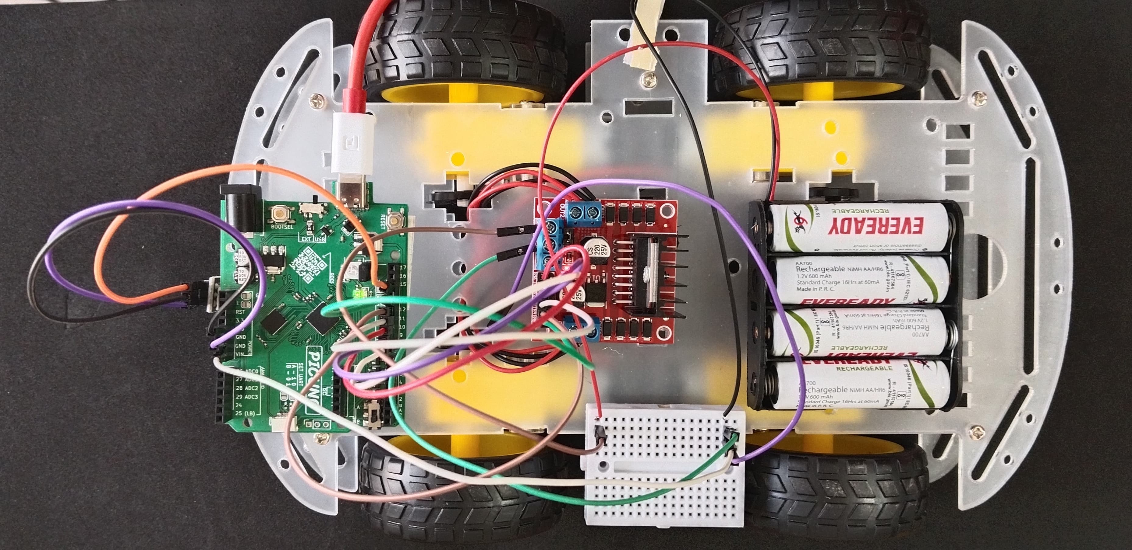
6.) Mount the Electronics: Finally, mount the PICUNO, the L298N motor driver board and tracking sensor (facing the track) onto the upper chassis, usually using screws/double tape. Position them such that to easily run wires to the motors.
ASSEMBLY OF 4-WHEEL CHASIS KIT:
1.) Prepare the Chassis: If your chassis parts are acrylic, they often come with a protective paper or plastic film. Peel this film off all the pieces.
2.) Mount the Motors: Attach the four yellow DC motors to the lower chassis plate. Use the brackets and long screws/nuts that came with the kit to secure them firmly in place.
3.) Attach the Wheels: Push the four main wheels onto the plastic shafts of the motors. They should be a snug fit.
4.) Attach the Upper Chassis: Use the Screws/nuts to attach the upper chassis firmly. This will work as a holder for other components to be placed.
5.) Mount the Battery Holder: Use screws to attach the 4xAA battery pack at the top of the upper chassis.
6.) Mount the Electronics: Finally, mount the PICUNO, the L298N motor driver board and tracking sensor (facing the track) onto the upper chassis, usually using screws/double tape. Position them such that to easily run wires to the motors.
CIRCUIT DIAGRAM:

- OUT1 & OUT2: Connect these two screw terminals to the outputs for the first motor and second motor (e.g., two wheels from left side). Connect the two wires (black) from both DC motors to OUT1 and other two wires (red) to OUT2.
- OUT3 & OUT4: Connect these two screw terminals to the outputs for the third and fourth motor (e.g., two wheels from right side). Connect the two wires (red) from both DC motors to OUT3 and other two wires (black) to OUT4.
- Connect the positive terminal (+) of the 4xAA battery pack to the 12V screw terminal.
- Connect the negative terminal (-) of the 4xAA battery pack to the GND screw terminal.
- Also connect the GND terminal on the L298N to a GND pin on the microcontroller to create a common ground.
- Connect the IN1 pin (Left side wheels) to GPIO 8.
- Connect the IN2 pin (Left side wheels) to GPIO 9.
- Connect the ENA pin (Left motors speed) to GPIO 10.
- Connect the IN1 pin (Right side wheels) to GPIO 11.
- Connect the IN2 pin (Right side wheels) to GPIO 12.
- Connect the ENB pin (Right motors speed) to GPIO 13.
NOTE: Remove the ENA and ENB jumpers on the L298N motor driver.
OPTIONAL: You can power the PICUNO using an external power supply (9V Battery) through DC Jack, once you have uploaded the code to the microcontroller.
- Connect the GND (G) pin to GND on board.
- Connect the VCC (V+) pin to 5V.
- Connect the Signal (S) pin to GPIO 15.
SCHEMATIC:
L298N Motor Driver:
OUT1 & OUT2 → Outputs for the Left side Motors.
OUT3 & OUT4 → Outputs for the Right side Motors.
12V → positive terminal (+) of 4xAA battery pack.
GND → negative terminal (-) of 4xAA battery pack → GND on PICUNO.
IN1 (Left side Motors) → GPIO 8
IN2 (Left side Motors) → GPIO 9
ENA (Left Motors speed) → GPIO 10
IN3 (Right side Motors) → GPIO 11
IN4 (Right side Motors) → GPIO 12
ENB (Right Motors speed) → GPIO 13
Tracking Sensor:
GND / (G) → GND
VCC / (V+) → 5V
Signal / (S) → GPIO 15
CODE -- C:
move(left_speed, right_speed) - A single function now controls both motors, making the main loop very clean.
if sensor_state == 1: - This is the core of the robot's "brain." It checks if the sensor is currently seeing the black line.
Turning Logic - The robot steers by moving one wheel while the other is stopped. move(70, 0) makes it pivot right, and move(0, 70) makes it pivot left. This creates the zig-zag motion that follows the edge of the line.
CODE -- PYTHON:
move(left_speed, right_speed) - A single function that controls both motors, making the main loop very clean. It takes a speed value for each wheel to perform complex movements like turning.
sensor_state = tracking_sensor.value() - This line reads the digital state of the tracking sensor. It will return 0 if the sensor sees a white surface and 1 if it sees a black surface.
if sensor_state == 1: - This is the core of the robot's "brain." It checks if the sensor is currently seeing the black line.
Turning Logic - The robot steers by moving one wheel while the other is stopped. move(70, 0) makes it pivot right, and move(0, 70) makes it pivot left. This creates the zig-zag motion that follows the edge of the line.to turn