LED Bar Graph Controlled By Potentiometer
HARDWARE REQUIRED:
- PICUNO Microcontroller board
- 1 × LED Bar Graph Display (Common Cathode)
- 10 × 220Ω resistors (Current limiting for LEDs)
- 1 × 10kΩ Potentiometer
- Jumper wires
- USB cable
DESCRIPTION:
This project demonstrates how to control the number of LEDs lit on a 10-segment LED bar graph (SB401010N) using a potentiometer. The analog value from the potentiometer is read and mapped to a value between 0 and 10 to represent the number of LEDs to light up. This simulates a live level or volume-style indicator.
CIRCUIT DIAGRAM:
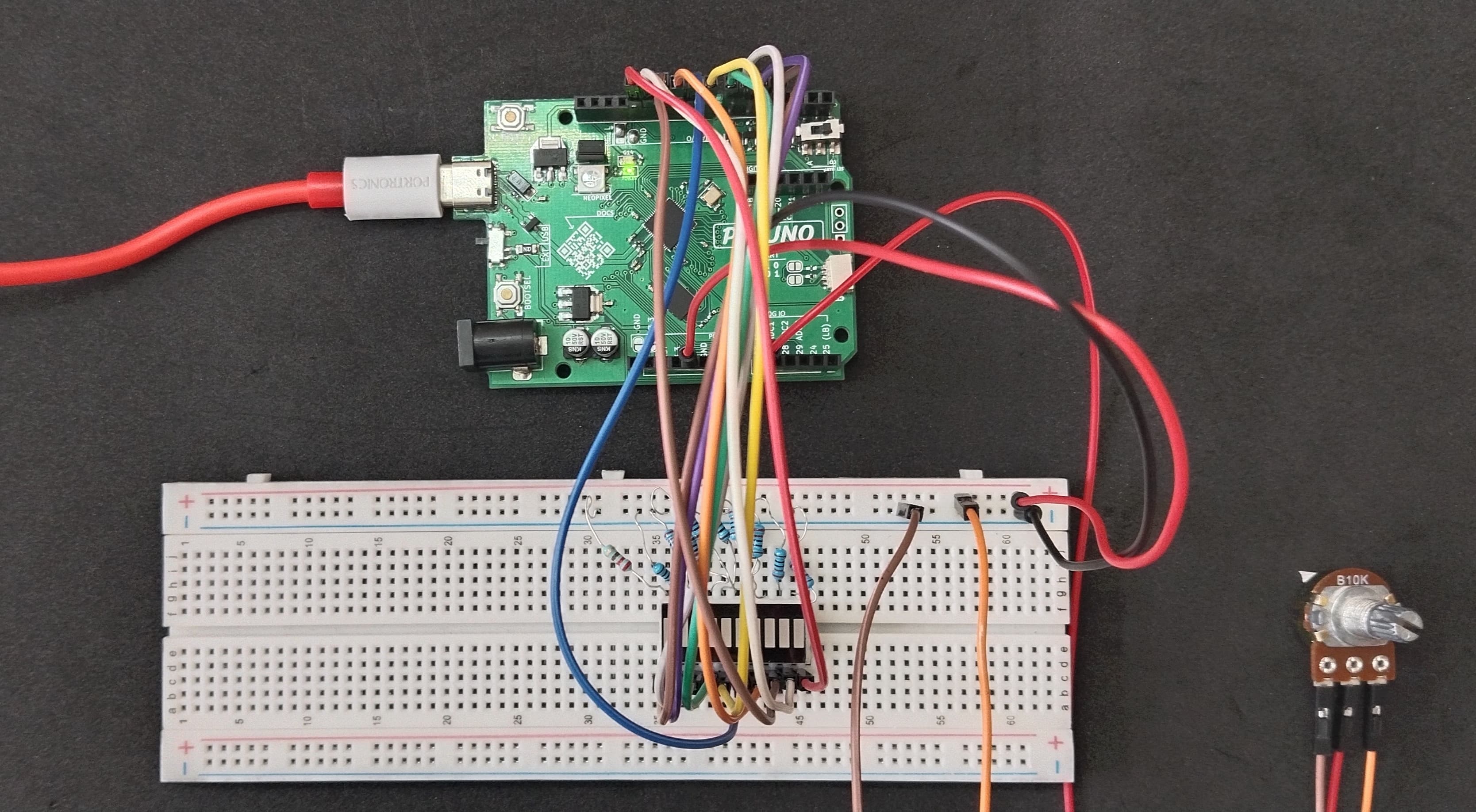
- Connect the PICUNO board to the computer using a USB cable.
- Connect each LED anode from 1-10 to GPIO 4 to 13 using 220Ω resistors.
- Connect all LED cathodes to GND through 220Ω resistors.
- Connect outer terminals of the potentiometer to VCC and GND, centre terminal to Analog pin A0 (Pin 26 in PICUNO).
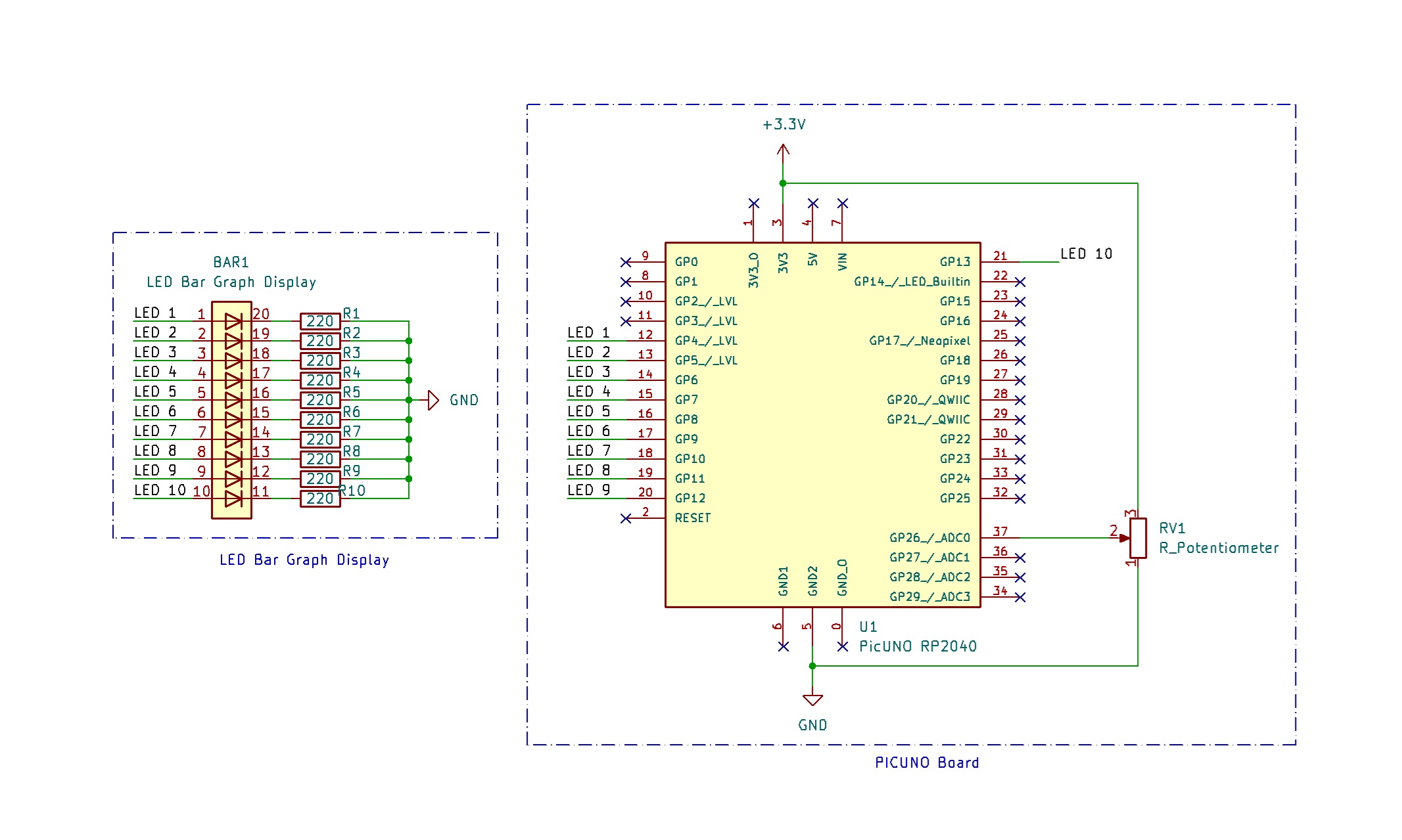
SCHEMATIC:
LED 1 anode → GPIO 4
LED 2 anode → GPIO 5
LED 3 anode → GPIO 6
LED 4 anode → GPIO 7
LED 5 anode → GPIO 8
LED 6 anode → GPIO 9
LED 7 anode → GPIO 10
LED 8 anode → GPIO 11
LED 9 anode → GPIO 12
LED 10 anode → GPIO 13
All LEDs cathode → 220Ω resistor → GND
Potentiometer Outer Terminals → VCC, GND
Potentiometer Centre Terminal → A0
CODE -- C:
const int ledPins[10] = {4, 5, 6, 7, 8, 9, 10, 11, 12, 13};
const int potPin = A0; // Potentiometer connected to A0
void setup() {
for (int i = 0; i < 10; i++) {
pinMode(ledPins[i], OUTPUT);
digitalWrite(ledPins[i], LOW); // All LEDs OFF initially
}
}
void loop() {
int potValue = analogRead(potPin); // Read 0–1023
int level = map(potValue, 0, 1023, 0, 10); // Scale to 0–10 LEDs
for (int i = 0; i < 10; i++) {
if (i < level)
digitalWrite(ledPins[i], HIGH); // ON (common cathode)
else
digitalWrite(ledPins[i], LOW); // OFF
}
delay(100); // Small delay to reduce flickering
}
ledPins[] - Stores all GPIOs connected to LED segments.
analogRead(potPin) - Reads the current voltage from the potentiometer.
map() - Scales the value to 0–10.
for loop - Turns ON LEDs up to that level and turns OFF the rest.
analogRead(potPin) - Reads the current voltage from the potentiometer.
map() - Scales the value to 0–10.
for loop - Turns ON LEDs up to that level and turns OFF the rest.
CODE -- PYTHON:
from machine import Pin, ADC
from time import sleep
led_pins = [Pin(i, Pin.OUT) for i in range(4, 14)]
pot = ADC(26)
while True:
pot_value = pot.read_u16() # Read 16-bit ADC value (0–65535)
level = int(pot_value / 65535 * 10) # Scale to 0–10
# Light up LEDs up to 'level'
for i in range(10):
if i < level:
led_pins[i].value(1) # ON (HIGH for common cathode)
else:
led_pins[i].value(0) # OFF
sleep(0.1)
led_pins = [Pin(i, Pin.OUT) for i in range(4, 14)] - Initializes GPIO 4 to 13 as outputs. Each connected to one LED segment (common cathode bar).
pot = ADC(26) - Creates an ADC object on GPIO 26 (A0 on PicUNO).
pot.read_u16() - Reads analog voltage from pot (0–65535).
level = int(pot_value / 65535 * 10) - Scales analog reading to a range of 0 to 10.
pot = ADC(26) - Creates an ADC object on GPIO 26 (A0 on PicUNO).
pot.read_u16() - Reads analog voltage from pot (0–65535).
level = int(pot_value / 65535 * 10) - Scales analog reading to a range of 0 to 10.