Laser-Tripwire Alarm System

HARDWARE REQUIRED:
- PICUNO Microcontroller board
- 1 × HW-486 Photoresistor Module
- 1 × HW-493 Laser Emitter Module
- 1 × Buzzer
- Jumper wires
- USB cable
DESCRIPTION:
This project creates a simple but effective security system. A laser beam is aimed at a photoresistor, creating an invisible "tripwire." The system first calibrates itself by measuring the normal amount of light hitting the sensor. If the beam is broken by someone walking through it, the amount of light hitting the sensor drops suddenly. The program detects this sharp change and triggers an alarm, sounding a buzzer to signal that the beam has been broken.
CIRCUIT DIAGRAM:
- Connect the VCC (+) (Middle) pin to 5V.
- Connect the GND (-) (Rightmost) pin to GND.
- Connect the Signal (S) (Leftmost) pin to GPIO 8.
- Connect the GND (-) pin to GND pin.
- Connect the VCC (+) pin to 5V.
- Connect the Signal (S) pin to Analog Pin A0 (GPIO 26)
- Connect the GND (-) pin to GND pin.
- Connect the VCC (+) pin to 5V.
- Connect the Signal (S) pin to GPIO 7.
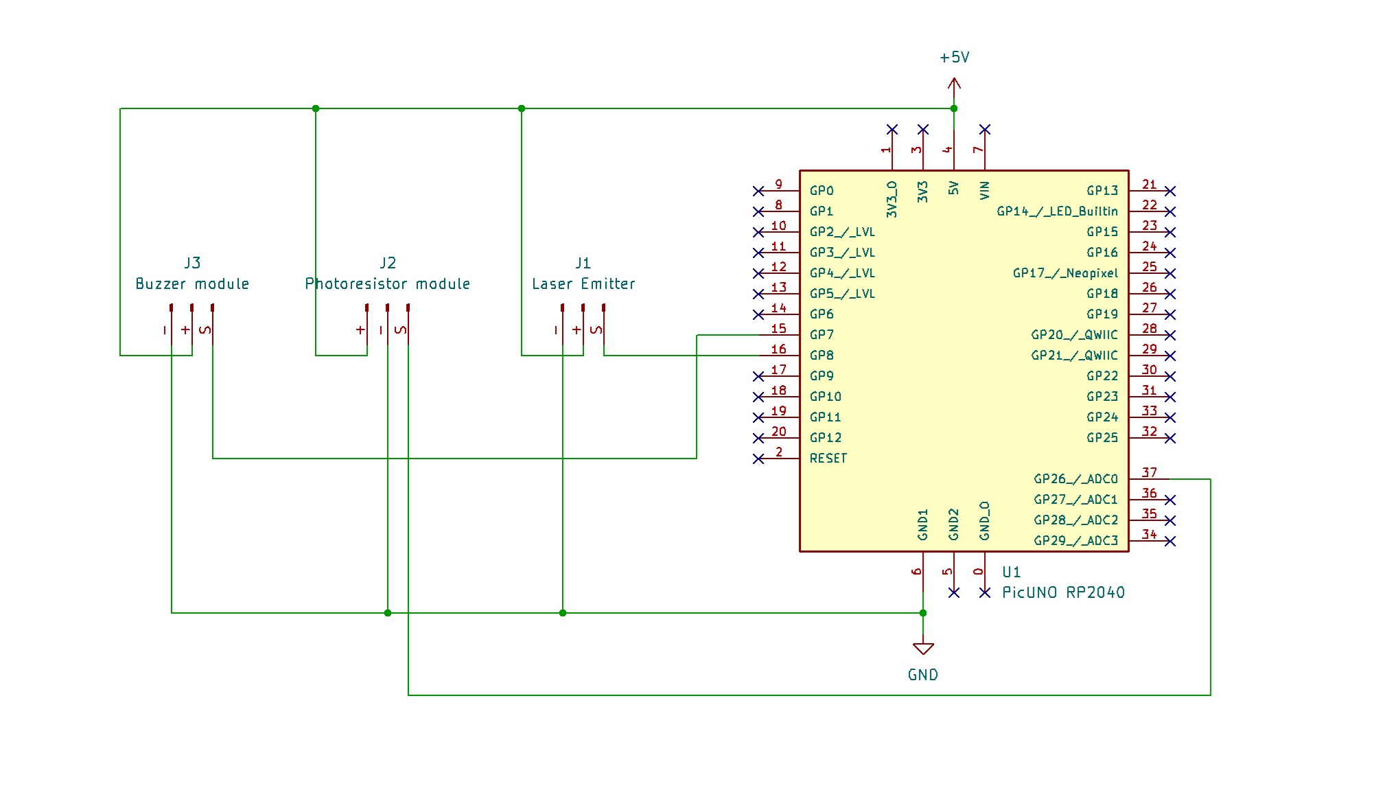
SCHEMATIC:
Laser Emitter Module:
VCC / (+) → 5V
GND / (-) → GND
Signal (S) → GPIO 8
Photoresistor Module:
VCC / (+) → 5V
GND / (-) → GND
Signal (S) → A0 (GPIO 26)
Buzzer Module:
VCC / (+) → 5V
GND / (-) → GND
Signal (S) → GPIO 7
CODE -- C:
const int LASER_PIN = 8;
const int LDR_PIN = A0;
const int BUZZER_PIN = 7;
int lightThreshold;
void setup() {
Serial.begin(9600);
pinMode(LASER_PIN, OUTPUT);
pinMode(LDR_PIN, INPUT);
pinMode(BUZZER_PIN, OUTPUT);
digitalWrite(LASER_PIN, HIGH);
Serial.println("Calibrating... Please do not break the beam.");
delay(2000);
int baselineLight = analogRead(LDR_PIN);
lightThreshold = baselineLight + 100;
Serial.print("Calibration complete. Baseline: ");
Serial.print(baselineLight);
Serial.print(". Alarm triggers above: ");
Serial.println(lightThreshold);
Serial.println("System Armed.");
}
void loop() {
int currentLight = analogRead(LDR_PIN);
if (currentLight > lightThreshold) {
Serial.print("ALARM! Beam broken. Reading: ");
Serial.println(currentLight);
digitalWrite(BUZZER_PIN, HIGH);
delay(200);
digitalWrite(BUZZER_PIN, LOW);
}
delay(100);
}
Calibration - The code first reads the "normal" light level from the photoresistor when the laser is hitting it. This is stored in the baselineLight variable.
lightThreshold - A trigger threshold is calculated based on the baseline reading. This makes the project work in different lighting conditions without changing the code.
analogRead(LDR_PIN) - Reads the Analog voltage from the photoresistor module, which corresponds to the brightness of the light hitting it.
if (currentLight > lightThreshold) - This is the core logic. It constantly checks if the current light reading has crossed the threshold, which happens when the beam is broken.
CODE -- PYTHON:
from machine import Pin, ADC
from time import sleep
laser = Pin(8, Pin.OUT)
ldr = ADC(Pin(26))
buzzer = Pin(7, Pin.OUT)
laser.high() # Turn the laser on
print("Calibrating... Please do not break the beam.")
sleep(2)
baseline_light = ldr.read_u16()
threshold = baseline_light + 5000
print(f"Calibration complete. Baseline: {baseline_light}. Threshold: {threshold}")
print("System Armed.")
while True:
current_light = ldr.read_u16()
if current_light > threshold:
print(f"ALARM! Beam broken. Reading: {current_light}")
buzzer.high()
sleep(0.2)
buzzer.low()
sleep(0.1)
Calibration - The script first turns on the laser and takes a baseline reading to set a threshold for the alarm.
ADC(Pin(26)) - Creates an Analog-to-Digital Converter object to read the voltage from the photoresistor.
ldr.read_u16() - Reads the Analog light level as a high-resolution number (0-65535).
if current_light > threshold - The main logic that continuously checks if the beam has been broken by comparing the live light reading to the calibrated threshold.
buzzer.high() / buzzer.low() - These lines turn the buzzer on and off quickly to create a short beep when the alarm is triggered.