Stepper Motor Speed And Direction Control
HARDWARE REQUIRED:
- PICUNO Microcontroller board
- 1 × 5V Stepper Motor
- 1 × ULN2003 Driver Board
- 1 × 10kΩ Potentiometer
- 1 × Push Button
- 1 × 10kΩ Resistor (Pull-down)
- Jumper wires
- USB cable
- 9V Battery with a snap connector (to power the board via the DC Jack)
DESCRIPTION:
This project provides precise real-time control over a 5V stepper motor. A potentiometer acts as a speed dial, allowing you to vary the motor's rotation speed smoothly. A separate push button is used to instantly toggle the motor's direction between clockwise and counter-clockwise. The code drives the motor using a half-step sequence, which provides smoother motion and double the resolution compared to full-stepping. This setup is a fundamental building block for robotics, CNC machines, and any project requiring precise positional control.
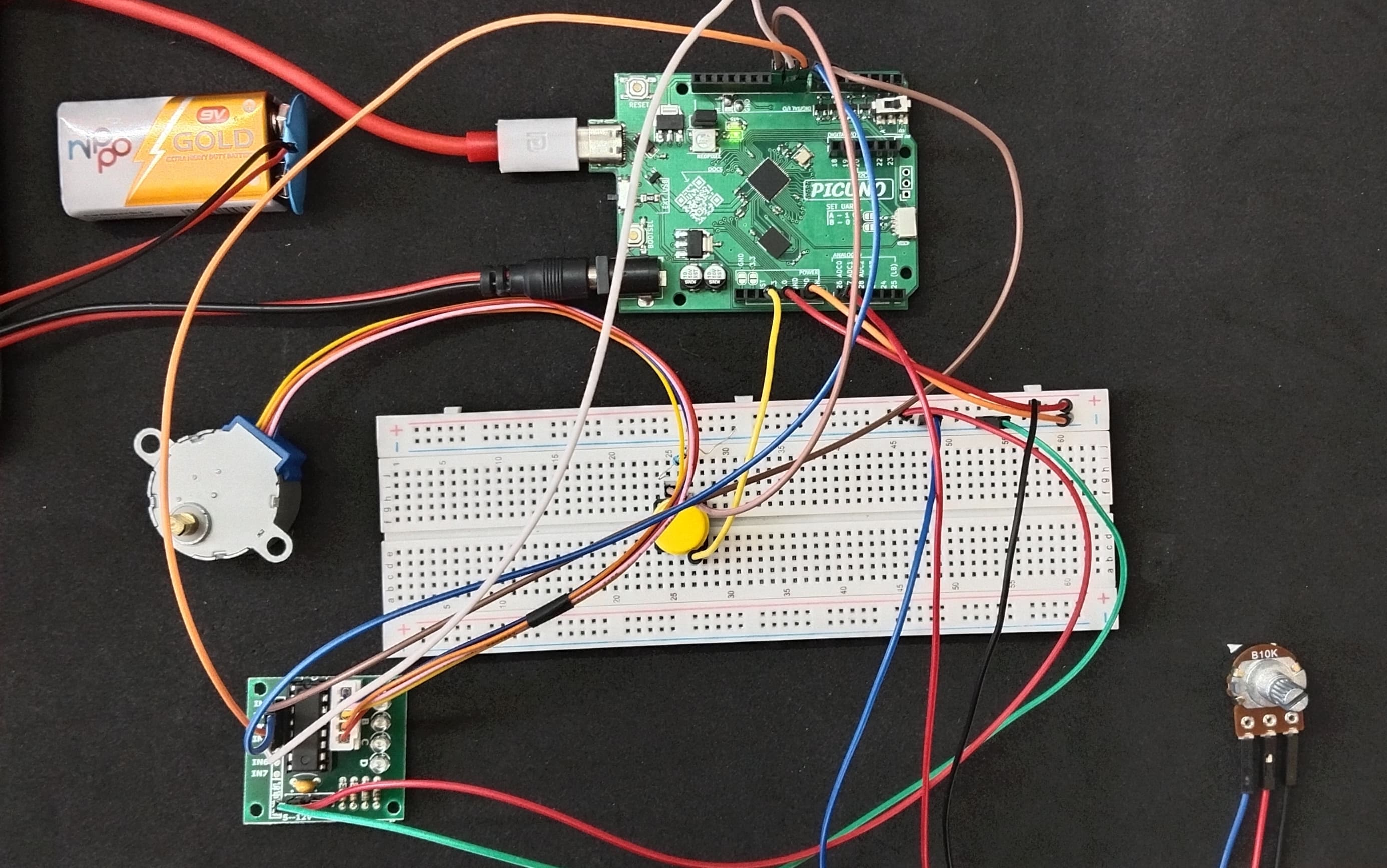
CIRCUIT DIAGRAM:
- Connect the Potentiometer centre pin to A0 (GPIO 26), and the outer pins to 3.3V and GND.
- Connect one leg of the Push Button to 3.3V.
- Connect other leg of the Push Button to GPIO 10 and connect a pull-down resistor of 10kΩ from GPIO 10 to GND.
- ULN2003 Driver Board:
- Connect IN1, IN2, IN3, IN4 to PICUNO pins GPIO 6, 7, 8, and 9 respectively.
- Connect the driver's + and GND pins to 5V and GND.
- Plug the stepper motor's connector into the socket on the driver board.
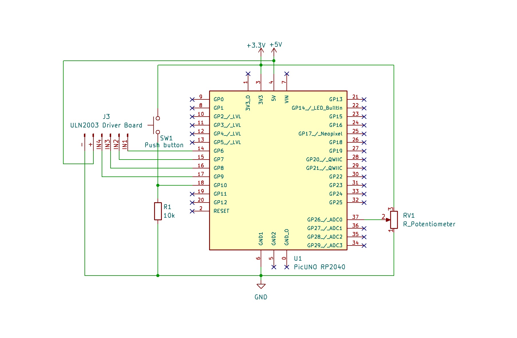
SCHEMATIC:
Potentiometer Centre Pin → A0 (GPIO 26)
Potentiometer Rightmost Pin → 3.3V
Potentiometer Leftmost Pin → GND
Push Button one side → 3.3V
Push Button other side → GPIO 10 → 10kΩ Resistor → GND
ULN2003 Driver & Power:
ULN2003 IN1 → PICUNO GPIO 6
ULN2003 IN2 → PICUNO GPIO 7
ULN2003 IN3 → PICUNO GPIO 8
ULN2003 IN4 → PICUNO GPIO 9
ULN2003 Power + Pin → 5V
ULN2003 Ground - Pin → GND
CODE -- C:
const int IN1 = 6;
const int IN2 = 7;
const int IN3 = 8;
const int IN4 = 9;
const int motorPins[] = {IN1, IN2, IN3, IN4};
const int potPin = A0;
const int buttonPin = 10;
// Stepper sequence (half-step mode)
const int step_sequence[8][4] = {
{1,0,0,0}, {1,1,0,0}, {0,1,0,0}, {0,1,1,0},
{0,0,1,0}, {0,0,1,1}, {0,0,0,1}, {1,0,0,1}
};
int current_dir = 1; // 1 = forward, -1 = backward
int last_btn_state = LOW;
int step_index = 0;
void move_step(int index) {
for (int i = 0; i < 4; i++) {
digitalWrite(motorPins[i], step_sequence[index][i]);
}
}
void setup() {
for (int i = 0; i < 4; i++) {
pinMode(motorPins[i], OUTPUT);
}
pinMode(buttonPin, INPUT_PULLUP);
}
void loop() {
// Check button press to toggle direction
int btn_state = digitalRead(buttonPin);
if (btn_state == LOW && last_btn_state == HIGH) {
current_dir *= -1;
delay(50); // debounce delay
}
last_btn_state = btn_state;
int pot_val = analogRead(potPin);
// map() is used to convert the 0-1023 pot range to a 2000-20000 microsecond delay range
long delay_us = map(pot_val, 0, 1023, 20000, 2000);
move_step(step_index);
delayMicroseconds(delay_us);
step_index = (step_index + current_dir + 8) % 8; // The +8 ensures the result is always positive
}
step_sequence - A 2D array that holds the 8 distinct ON/OFF patterns for the four motor coils to achieve a half-step rotation.
move_step() - A function that takes a step number (0-7) and applies the corresponding pattern to the motor pins.
map(pot_val, 0, 1023, 20000, 2000) - This line reads the potentiometer value (0-1023) and scales it to a delay in microseconds. Note that the output range is reversed (20000 to 2000), so a low pot value gives a long delay (slow speed) and a high pot value gives a short delay (fast speed).
step_index = (step_index + current_dir + 8) % 8 - This line advances the motor to the next step in the sequence. It adds 1 or -1 depending on the direction and uses the modulo (%) operator to make sure the index wraps around (from 7 to 0, or 0 to 7), creating continuous rotation.
CODE -- PYTHON:
from machine import Pin, ADC
from time import sleep
# Stepper pins (IN1-IN4)
IN1 = Pin(6, Pin.OUT)
IN2 = Pin(7, Pin.OUT)
IN3 = Pin(8, Pin.OUT)
IN4 = Pin(9, Pin.OUT)
# Potentiometer (speed control)
pot = ADC(26) # A0
# Direction button
button = Pin(10, Pin.IN)
# Stepper sequence (half-step mode)
step_sequence = [
[1,0,0,0],
[1,1,0,0],
[0,1,0,0],
[0,1,1,0],
[0,0,1,0],
[0,0,1,1],
[0,0,0,1],
[1,0,0,1],
]
current_dir = 1 # 1 = forward, -1 = backward
last_btn = 0
step_index = 0
def move_step(index):
pins = step_sequence[index]
IN1.value(pins[0])
IN2.value(pins[1])
IN3.value(pins[2])
IN4.value(pins[3])
while True:
# Check button press to toggle direction
if button.value() == 1 and last_btn == 0:
current_dir *= -1
sleep(0.2) # debounce delay
last_btn = button.value()
# Read potentiometer value (0–65535) → delay
pot_val = pot.read_u16()
delay = 0.002 + (1 - pot_val / 65535) * 0.018 # range: 2ms to 20ms
move_step(step_index)
sleep(delay)
step_index = (step_index + current_dir) % 8
step_sequence - A list of lists defining the 8 patterns for the half-step sequence. 1 is ON, 0 is OFF.
move_step() - This function simplifies the main loop by setting the four motor pins based on the current step in the sequence.
current_dir *= -1 - This line cleverly toggles the direction. It multiplies the current_dir variable by -1, flipping it between 1 (forward) and -1 (backward).
delay = 0.002 + (1 - (pot_val / 65535)) * 0.018 - This line maps the 16-bit potentiometer value to a delay between steps. The (1 - ...) part inverts the logic, so a higher pot reading results in a shorter delay and faster speed.
step_index = (step_index + current_dir) % 8 - This is the core of the movement. It advances the index forward or backward through the step_sequence and uses the modulo (%) operator to wrap the index back to 0 when it goes past 7 (or back to 7 from 0), ensuring continuous rotation.