Automated Thermostat With Stepper Motor (Fan)
HARDWARE REQUIRED:
- PICUNO Microcontroller board
- 1 × HW-503 Digital Temperature Sensor
- 1 × 5V Stepper Motor
- 1 × ULN2003 Driver Board
- 1 × 4xAA Battery Pack (For external supply)
- Jumper wires
- USB cable
DESCRIPTION:
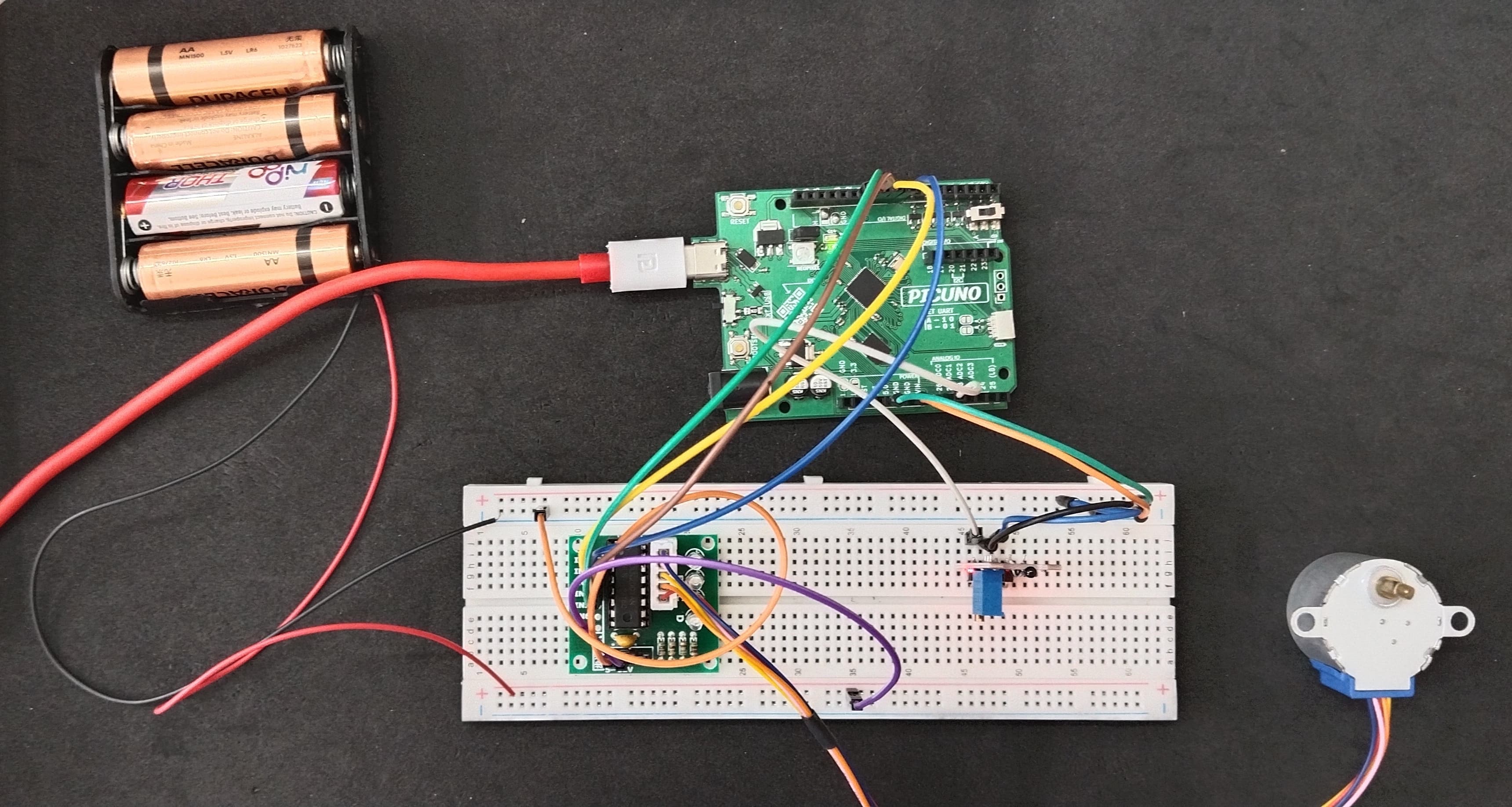
This project creates a smart thermostat that controls a "fan" made from a stepper motor. The system uses a manual calibration method to get an accurate temperature reading from the sensor. When the ambient temperature rises above a setpoint, the program activates the stepper motor, causing it to spin continuously like a fan. When the temperature drops, the fan automatically turns off. This project demonstrates a real-world closed-loop control system and the importance of calibrating sensors.
NOTE:
The component has an NTC Thermistor module.
Core Component: The black, bead-like component is a special resistor whose resistance changes predictably with temperature.
Key Principle: "NTC" stands for Negative Temperature Coefficient. This simply means as the sensor gets hotter, its electrical resistance gets lower. So the voltage reading also gets lower.
The red circuit board is a "voltage divider." It converts the sensor's changing resistance into a changing voltage. The blue knob allows to set a temperature threshold.
CIRCUIT DIAGRAM:
- Connect IN1, IN2, IN3, IN4 to PICUNO pins GPIO 15, 16, 18, and 19 respectively.
- Connect the driver's + and GND pins to positive terminal of the 4xAA Battery pack and GND respectively.
- Plug the stepper motor's connector into the socket on the driver board.
- Connect the negative terminal of the 4xAA Battery Pack to Common GND on breadboard.
- Connect the GND (G) pin to GND on board.
- Connect the VCC (+) pin to 5V on board.
- Connect the Analog Output (AO) pin to A0 (GPIO 26).
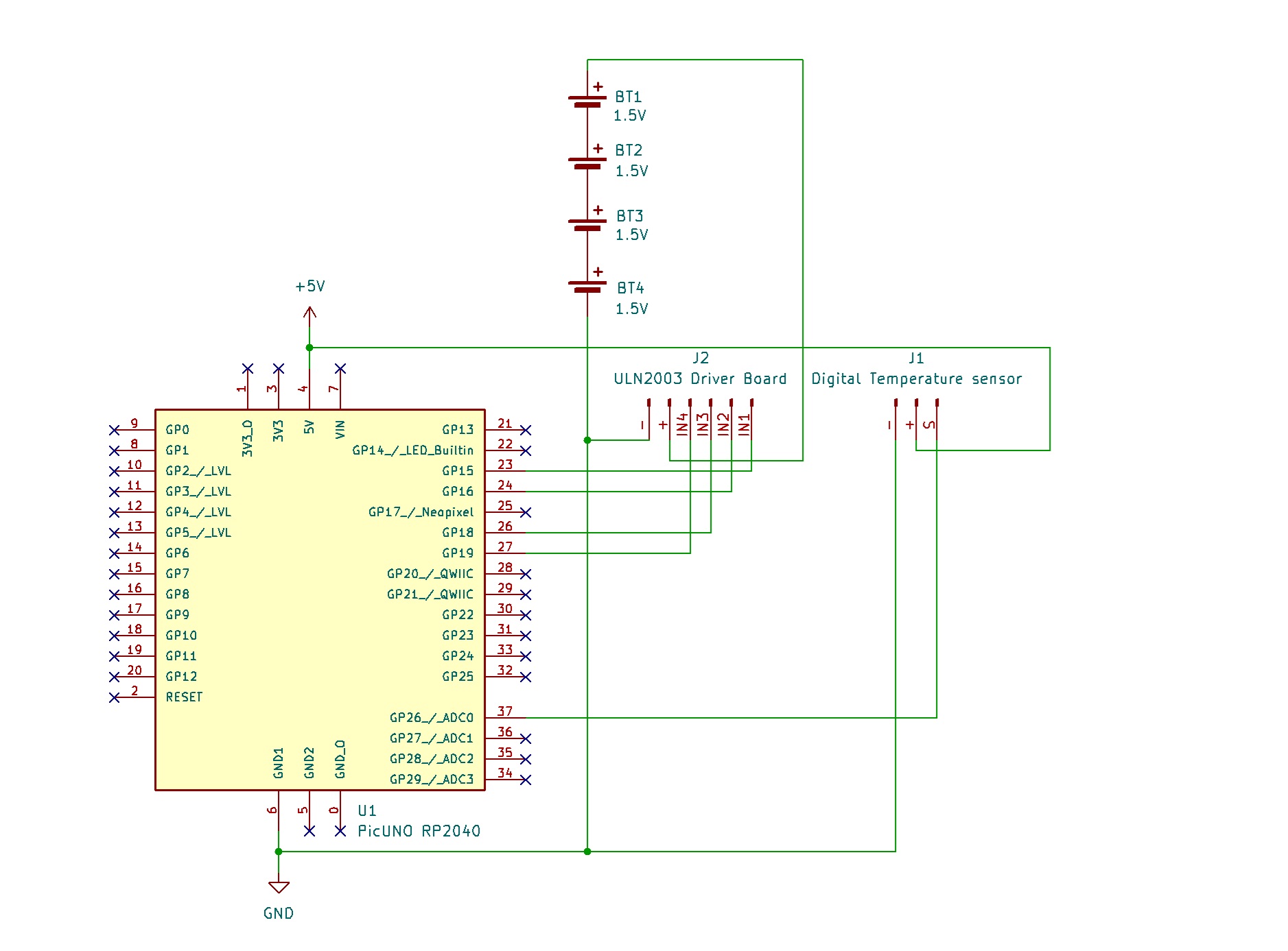
SCHEMATIC:
ULN2003 Driver & Power:
ULN2003 IN1 → PICUNO GPIO 15
ULN2003 IN2 → PICUNO GPIO 16
ULN2003 IN3 → PICUNO GPIO 18
ULN2003 IN4 → PICUNO GPIO 19
ULN2003 Power + Pin → 4xAA Battery Pack (+)
ULN2003 Ground - Pin → GND
Digital Temperature Sensor:
GND (G) pin → GND
VCC (+) pin → 5V
AO pin → A0 (GPIO 26)
Common Ground Connection:
4xAA Battery Pack (-) → PICUNO Board GND
CODE -- C:
const int TEMP_SENSOR_PIN = A0;
const int IN1 = 8;
const int IN2 = 9;
const int IN3 = 10;
const int IN4 = 11;
const float SETPOINT_TEMP = 28.0;
const float HYSTERESIS = 1.0;
const int ROOM_TEMP_READING = 540;
const int WARM_TEMP_READING = 500;
const float ROOM_TEMP_C = 26.0;
const float WARM_TEMP_C = 33.0;
const int step_sequence[8][4] = {
{1, 0, 0, 1}, {1, 0, 0, 0}, {1, 1, 0, 0}, {0, 1, 0, 0},
{0, 1, 1, 0}, {0, 0, 1, 0}, {0, 0, 1, 1}, {0, 0, 0, 1}
};
int motor_pins[4] = {IN1, IN2, IN3, IN4};
int current_motor_step = 0;
// --- State & Timer Variables ---
bool isFanOn = false;
unsigned long lastTempCheckTime = 0;
const long tempCheckInterval = 1000; // Check temperature every 1 second (1000 ms)
void setup() {
Serial.begin(9600);
for (int i = 0; i < 4; i++) {
pinMode(motor_pins[i], OUTPUT);
}
Serial.println("Thermostat Ready. Monitoring temperature...");
}
void loop() {
if (millis() - lastTempCheckTime >= tempCheckInterval) {
// Read and map the temperature value
int currentReading = analogRead(TEMP_SENSOR_PIN);
float temperatureC = map(currentReading, ROOM_TEMP_READING, WARM_TEMP_READING, ROOM_TEMP_C, WARM_TEMP_C);
Serial.print("Current Temp: ");
Serial.print(temperatureC);
Serial.println(" C");
// Check if the fan state needs to change
if (temperatureC > SETPOINT_TEMP) {
if (!isFanOn) {
Serial.println("--> Temperature HIGH. Turning fan ON.");
isFanOn = true;
}
} else if (temperatureC < SETPOINT_TEMP - HYSTERESIS) {
if (isFanOn) {
Serial.println("--> Temperature NORMAL. Turning fan OFF.");
isFanOn = false;
}
}
lastTempCheckTime = millis(); // Reset the timer
}
if (isFanOn) {
current_motor_step++;
if (current_motor_step > 7) {
current_motor_step = 0;
}
for (int i = 0; i < 4; i++) {
digitalWrite(motor_pins[i], step_sequence[current_motor_step][i]);
}
delay(2); // The speed control delay
} else {
for (int i = 0; i < 4; i++) {
digitalWrite(motor_pins[i], LOW);
}
}
}
Manual Calibration (map()) - This is the key to getting an accurate reading. The code uses the map() function to convert the raw analogRead() values (e.g., 540-500) into a realistic Celsius range (e.g., 26-33°C) based on your real-world testing.
step_sequence array - This array holds the 8 specific ON/OFF patterns for the motor's four coils. Cycling through them creates smooth rotation.
Dedicated Rotation Loop - When the temperature is high, the code enters a while loop that focuses only on running the motor logic with a delay(2), ensuring it has the perfect timing to spin without getting stuck.
CODE -- PYTHON:
from machine import Pin, ADC
from time import sleep_ms
TEMP_SENSOR_PIN = 26
motor_pins = [Pin(p, Pin.OUT) for p in [8, 9, 10, 11]]
SETPOINT_TEMP = 28.0
HYSTERESIS = 1.0
ROOM_TEMP_READING = 34000
WARM_TEMP_READING = 30000
ROOM_TEMP_C = 26.0
WARM_TEMP_C = 33.0
step_sequence = [[1,0,0,1],[1,0,0,0],[1,1,0,0],[0,1,0,0],[0,1,1,0],[0,0,1,0],[0,0,1,1],[1,0,0,1]]
current_motor_step = 0
temp_sensor = ADC(Pin(TEMP_SENSOR_PIN))
print("Thermostat Ready (Calibrated).")
# --- Helper Function ---
def map_value(x, in_min, in_max, out_min, out_max):
return (x - in_min) * (out_max - out_min) / (in_max - in_min) + out_min
# --- Main Loop ---
while True:
current_reading = temp_sensor.read_u16()
temperatureC = map_value(current_reading, ROOM_TEMP_READING, WARM_TEMP_READING, ROOM_TEMP_C, WARM_TEMP_C)
print(f"Current Temp: {temperatureC:.2f} C")
if temperatureC > SETPOINT_TEMP:
print("--> Temperature HIGH. Fan is ON.")
while temperatureC > SETPOINT_TEMP - HYSTERESIS:
current_motor_step = (current_motor_step + 1) % 8
for i in range(4):
motor_pins[i].value(step_sequence[current_motor_step][i])
sleep_ms(2)
# Re-check temperature to see if we should stop
current_reading = temp_sensor.read_u16()
temperatureC = map_value(current_reading, ROOM_TEMP_READING, WARM_TEMP_READING, ROOM_TEMP_C, WARM_TEMP_C)
print("--> Temperature NORMAL. Turning fan OFF.")
for pin in motor_pins:
pin.value(0) # De-energize motor
sleep_ms(1000)
Manual Calibration (map_value) - The code uses a custom map_value function to convert the raw 16-bit ADC values (e.g., 34000-30000) into a Celsius range based on your real-world calibration, making the reading accurate for your specific sensor.
step_sequence list - Holds the 8 electrical patterns that are sent to the four motor pins in sequence to create rotation.
Dedicated Rotation Loop - Just like the Arduino version, when the fan needs to be on, the code enters a focused while loop that does nothing but step the motor with a 2ms delay, ensuring smooth, uninterrupted rotation.