Flame Detection Alarm With LCD Display
HARDWARE REQUIRED:
- PICUNO Microcontroller board
- 1 × 16x2 I2C LCD Display
- 1 × Flame Sensor Module
- 1 × LED
- 1 × 220Ω resistor (current-limiting)
- 1 × Buzzer
- Jumper wires
- USB cable
- 9V Battery with a snap connector (to power the board via the DC Jack)
DESCRIPTION:
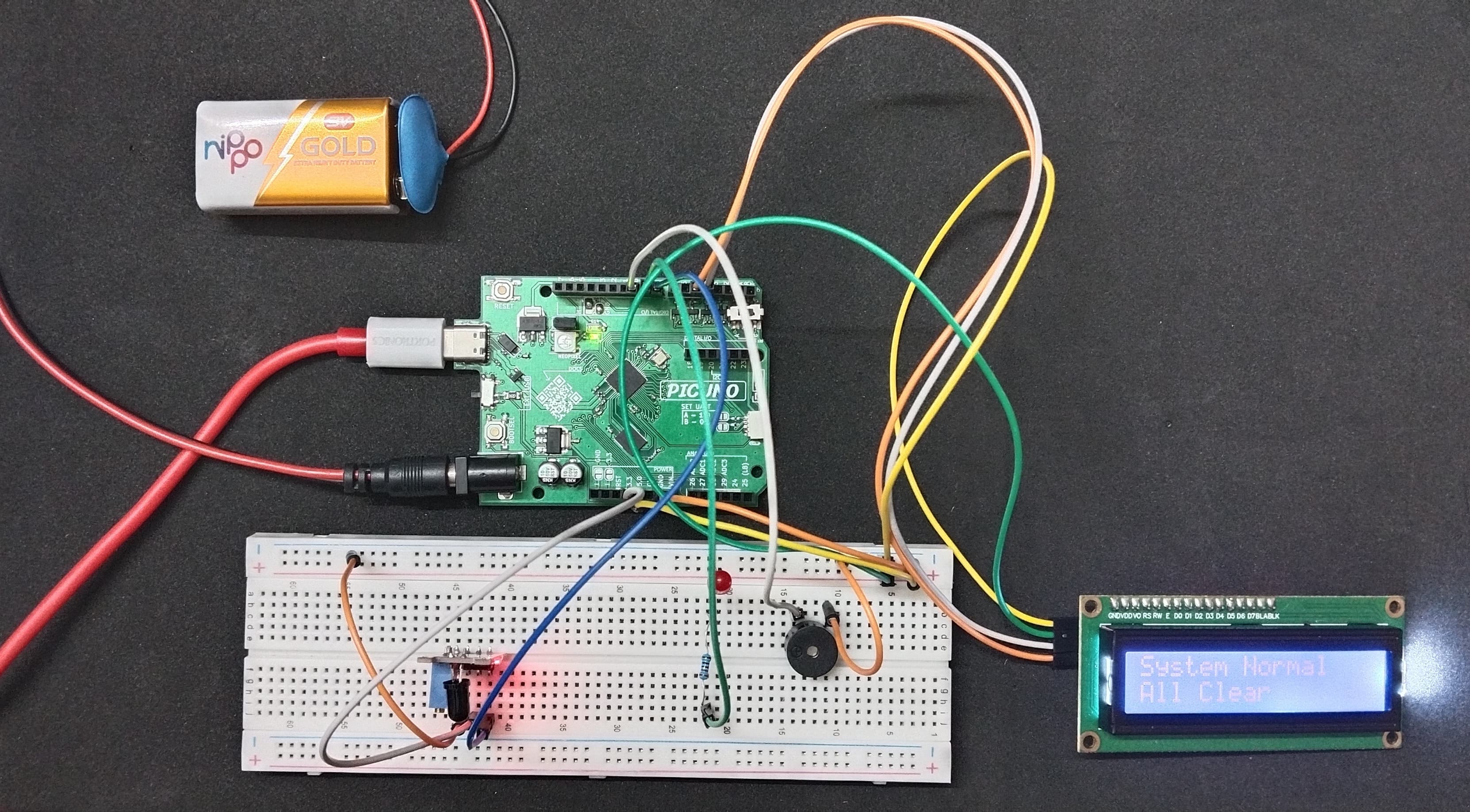
This project creates a comprehensive flame alarm that provides both audible and visual alerts. The system uses a flame sensor module to continuously monitor the environment for fire. When a flame is detected, the system activates an audible alarm through a buzzer, turns on a visual alert LED, and displays a prominent "ALARM! Flame Detected!" message on an I2C LCD screen. When the flame is no longer present, the alarm automatically silences and the screen reverts to a "System Normal" status.
LIBRARIES REQUIRED:
For C / Arduino IDE:
- Wire.h: Manages I2C communication (usually included by default).
- LiquidCrystal_I2C.h: The driver library for the I2C LCD module.
- i2c_lcd.py: The custom library file saved to the PICUNO board.
- The code also uses the built-in machine and time modules.
CIRCUIT DIAGRAM:

- Connect the anode of LED to GPIO 9 through 220Ω resistor and the cathode of the LED to GND.
- Connect the positive terminal of the Buzzer to GPIO 10 and negative terminal of the buzzer to GND.
- Connect the LCD Module's GND pin to a GND pin on board.
- Connect the LCD Module's VCC pin to the 5V pin on board.
- Connect the LCD Module's SDA pin GPIO 4 (SDA Pin on PICUNO).
- Connect the LCD Module's SCL pin GPIO 5 (SCL Pin on PICUNO).
- Flame Sensor Module:
- Connect the + pin to 3.3V pin on the board.
- Connect the GND pin to GND pin on board.
- Connect the DO pin to GPIO 8.
SCHEMATIC:
LED Anode → 220Ω → GPIO 9
LED Cathode → GND
Buzzer +ve terminal → GPIO 10
Buzzer -ve terminal → GND
LCD VCC → 5V
LCD GND → GND
LCD SDA → GPIO 4 (Board SDA Pin)
LCD SCL → GPIO 5 (Board SCL Pin)
Flame Sensor Module:
VCC → 3.3V
GND → GND
DO → GPIO 8
CODE -- C:
#include <Wire.h>
#include <LiquidCrystal_I2C.h>
// Define the pins
const int SENSOR_PIN = 8;
const int BUZZER_PIN = 10;
const int LED_PIN = 9;
// Setup the LCD object (address 0x27, 16 columns, 2 rows)
LiquidCrystal_I2C lcd(0x27, 16, 2);
// Variable to track the last state of the sensor
int lastFlameState = HIGH;
void setup() {
pinMode(SENSOR_PIN, INPUT);
pinMode(BUZZER_PIN, OUTPUT);
pinMode(LED_PIN, OUTPUT);
// Initialize the LCD
lcd.init();
lcd.backlight();
// Initial message
lcd.setCursor(0, 0);
lcd.print("System Normal");
lcd.setCursor(0, 1);
lcd.print("All Clear");
}
void loop() {
// Read the sensor's current state
int currentFlameState = digitalRead(SENSOR_PIN);
// Only update everything if the state has changed
if (currentFlameState != lastFlameState) {
if (currentFlameState == LOW) { // Flame is detected
lcd.clear();
lcd.setCursor(0, 0);
lcd.print("ALARM!");
lcd.setCursor(0, 1);
lcd.print("Flame Detected!");
digitalWrite(BUZZER_PIN, HIGH);
digitalWrite(LED_PIN, HIGH);
} else { // Flame is gone
lcd.clear();
lcd.setCursor(0, 0);
lcd.print("System Normal");
lcd.setCursor(0, 1);
lcd.print("All Clear");
digitalWrite(BUZZER_PIN, LOW);
digitalWrite(LED_PIN, LOW);
}
}
// Update the last state for the next loop
lastFlameState = currentFlameState;
delay(100);
}
int lastFlameState = HIGH; - This variable stores the previous state of the sensor so the code knows if anything has changed. We start it at HIGH (no flame).
if (currentFlameState != lastFlameState) - The code inside this block only runs when the sensor's state changes (from seeing a flame to not seeing one, or vice-versa). This prevents the LCD from flickering.
if (currentFlameState == LOW) - The flame sensor's digital pin goes LOW when it detects a flame. This if statement checks for that condition to trigger the alarm.
digitalWrite(BUZZER_PIN, HIGH); - This line activates the buzzer and LED when the alarm condition is met. The else block handles turning them off.
CODE -- PYTHON:
from machine import Pin, I2C
import time
from i2c_lcd import I2cLcd
# Setup all the pins
sensor = Pin(8, Pin.IN)
buzzer = Pin(10, Pin.OUT)
led = Pin(9, Pin.OUT)
# Setup the LCD
i2c = I2C(0, scl=Pin(5), sda=Pin(4))
lcd = I2cLcd(i2c, 0x27, 2, 16)
# Variable to track the last state
last_state = 1 # 1 = HIGH = No Flame
# Initial message
lcd.putstr("System Normal\nAll Clear")
while True:
current_state = sensor.value()
# Only update if the state has changed
if current_state != last_state:
lcd.clear()
if current_state == 0: # Flame is detected (LOW)
lcd.putstr("ALARM!\nFlame Detected!")
buzzer.value(1)
led.value(1)
else: # Flame is gone (HIGH)
lcd.putstr("System Normal\nAll Clear")
buzzer.value(0)
led.value(0)
# Update the last state for the next loop
last_state = current_state
time.sleep_ms(100)
last_state = 1 - This variable is used to remember the last state of the sensor to prevent screen flicker. We assume the starting state is 1 (HIGH, no flame).
if current_state != last_state: - This is the most important line. It ensures the code to update the LCD and alarms only runs when the sensor's state actually changes.
if current_state == 0: - Checks if the sensor has detected a flame (a LOW signal).
lcd.putstr("...") - This function from the LCD library prints the status message to the screen. The \n character creates a new line.