Keypad Combination Lock With LCD Display
HARDWARE REQUIRED:
- PICUNO Microcontroller board
- 1 × 4x4 Button Matrix Module
- 1 × HW-480 Two-colour LED Module
- 1 × SG90 Servo Motor
- 1 × I2C LCD Display
- 1 × 4xAA Battery Pack (For external supply)
- 1 × Buzzer
- Jumper wires
- USB cable
DESCRIPTION:
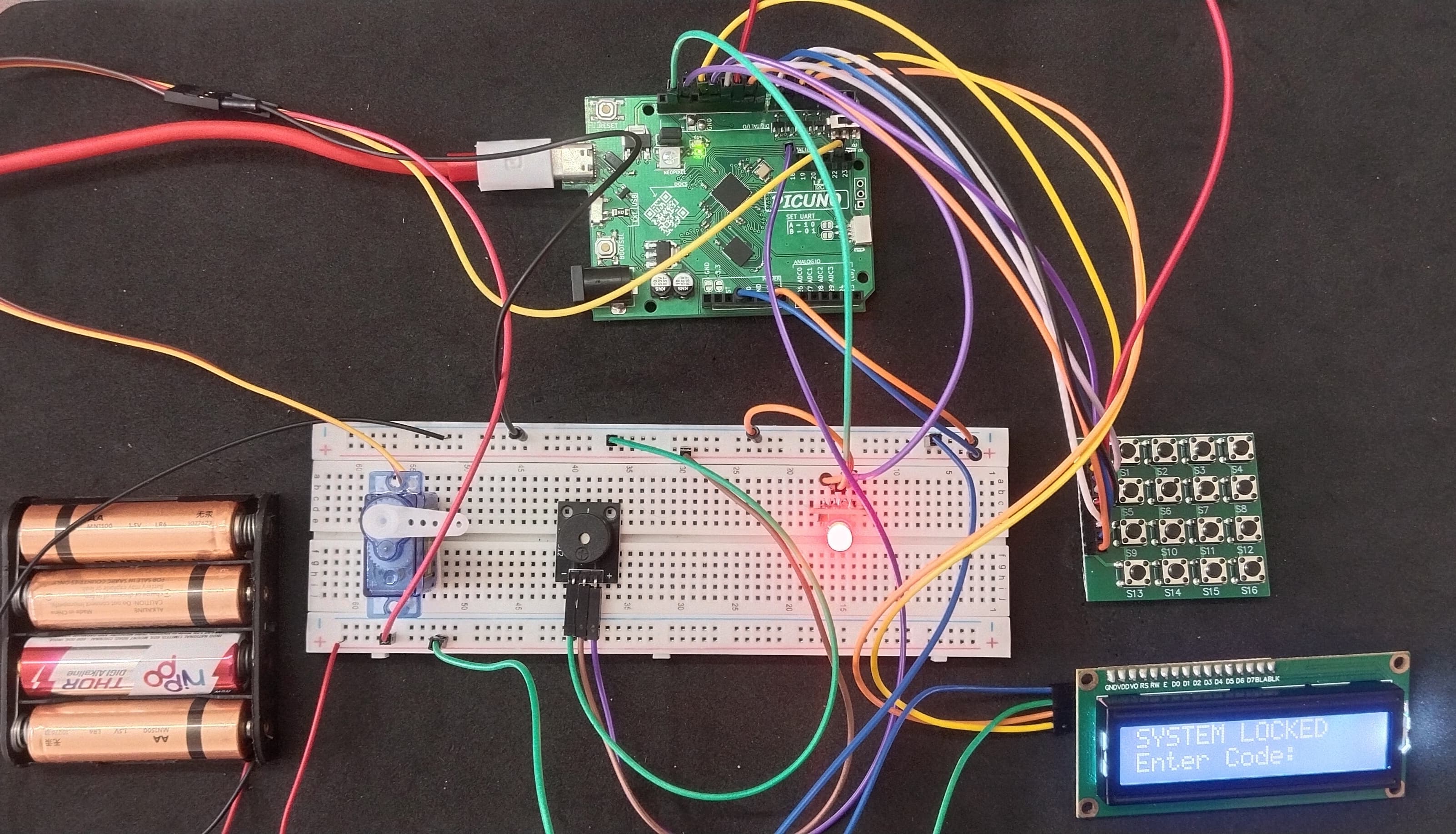
This project creates a digital safe that requires a secret code to open. The user enters a code on the 4x4 keypad, and the LCD provides real-time feedback, showing asterisks for each digit entered. If the correct code is entered, the LCD displays "ACCESS GRANTED," a servo unlocks, and a success tone plays. If the code is incorrect, the LCD shows "ACCESS DENIED," and a failure alarm sounds.
CIRCUIT DIAGRAM:
- Connect the LCD Module's GND pin to GND.
- Connect the LCD Module's VCC pin to the Positive (+) terminal of the 4xAA Battery Pack.
- Connect the LCD Module's SDA pin GPIO 4 (SDA Pin on PICUNO).
- Connect the LCD Module's SCL pin GPIO 5 (SCL Pin on PICUNO).
- Connect the Servo's VCC (Red) pin to the Positive (+) terminal of the 4xAA Battery Pack.
- Connect the Servo's GND (Brown) pin to GND.
- Connect the Servo's Signal (Yellow) pin to GPIO 22.
- Connect the negative terminal of the 4xAA Battery Pack to Common GND on breadboard.
- Connect the Row pins (5-8) to GPIO 6, 7, 8 and 9 respectively.
- Connect the Column pins (1-4) to GPIO 10, 11, 12 and 13 respectively.
- Connect the Green (G) pin to GPIO 16.
- Connect the Red (R) pin to GPIO 15.
- Connect the GND (-) pin to GND.
- Connect the GND (-) pin to GND pin.
- Connect the VCC (+) pin to 5V.
- Connect the Signal (S) pin to GPIO 18.
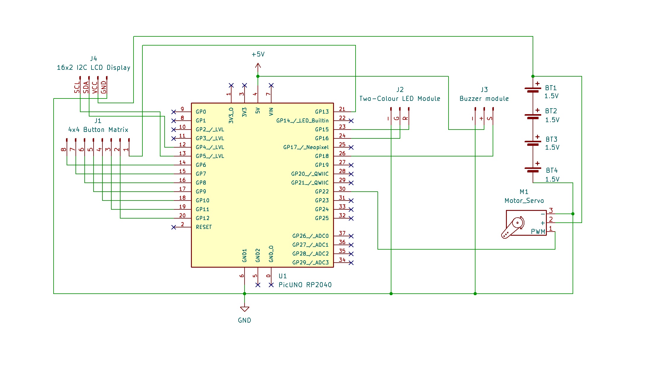
SCHEMATIC:
I2C LCD Display:
LCD VCC → 4xAA Battery Pack (+)
LCD GND → GND
LCD SDA → GPIO 4 (Board SDA Pin)
LCD SCL → GPIO 5 (Board SCL Pin)
Servo Motor:
VCC (Red Wire) → 4xAA Battery Pack (+)
GND (Brown Wire) → GND
Signal (Yellow Wire) → GPIO 22
Two-colour LED Module:
Green LED (G) → GPIO 16
Red LED (R) → GPIO 15
GND (-) → GND
4x4 Button Matrix Module:
Pin 1 (Column 4) → GPIO 13
Pin 2 (Column 3) → GPIO 12
Pin 3 (Column 2) → GPIO 11
Pin 4 (Column 1) → GPIO 10
Pin 5 (Row 1) → GPIO 9
Pin 6 (Row 2) → GPIO 8
Pin 7 (Row 3) → GPIO 7
Pin 8 (Row 4) → GPIO 6
Buzzer Module:
VCC / (+) → 5V
GND / (-) → GND
Signal (S) → GPIO 18
Common Ground Connection:
4xAA Battery Pack (-) → PICUNO Board GND
CODE -- C:
#include <Wire.h>
#include <LiquidCrystal_I2C.h>
#include <Servo.h>
const int GREEN_LED_PIN = 16;
const int RED_LED_PIN = 15;
const int BUZZER_PIN = 18;
const int SERVO_PIN = 22;
const byte ROWS = 4;
const byte COLS = 4;
char keys[ROWS][COLS] = {
{'1','2','3','A'},
{'4','5','6','B'},
{'7','8','9','C'},
{'*','0','#','D'}
};
byte rowPins[ROWS] = {6, 7, 8, 9};
byte colPins[COLS] = {10, 11, 12, 13};
// --- LCD & Servo Setup ---
LiquidCrystal_I2C lcd(0x27, 16, 2);
Servo myServo;
const int position_locked = 1;
const int position_unlocked = 90;
// --- Lock Settings ---
const int codeLength = 4;
char secretCode[codeLength + 1] = "1234";
char enteredCode[codeLength + 1] = "";
int codeIndex = 0;
// --- Helper Functions ---
void play_tone(int freq, int duration_ms) {
tone(BUZZER_PIN, freq, duration_ms);
}
void update_lcd_locked() {
lcd.clear();
lcd.setCursor(0, 0);
lcd.print("SYSTEM LOCKED");
lcd.setCursor(0, 1);
lcd.print("Enter Code:");
}
void lock_safe(bool silent) {
myServo.write(position_locked);
digitalWrite(GREEN_LED_PIN, LOW);
digitalWrite(RED_LED_PIN, HIGH);
update_lcd_locked();
if (!silent) {
play_tone(500, 200);
}
}
void unlock_safe() {
myServo.write(position_unlocked);
digitalWrite(RED_LED_PIN, LOW);
digitalWrite(GREEN_LED_PIN, HIGH);
lcd.clear();
lcd.setCursor(0, 0);
lcd.print("ACCESS GRANTED");
play_tone(2500, 100);
delay(100);
play_tone(3000, 100);
delay(5000);
lock_safe(false);
}
void fail_sequence() {
digitalWrite(RED_LED_PIN, HIGH);
lcd.clear();
lcd.setCursor(0, 0);
lcd.print("ACCESS DENIED");
play_tone(200, 500);
delay(2000);
update_lcd_locked();
}
void reset_code() {
codeIndex = 0;
enteredCode[0] = '\\0';
}
// --- NEW, IMPROVED get_key() FUNCTION ---
char get_key() {
for (byte r = 0; r < ROWS; r++) {
digitalWrite(rowPins[r], LOW); // Activate one row
for (byte c = 0; c < COLS; c++) {
if (digitalRead(colPins[c]) == LOW) {
delay(50); // Debounce delay
if (digitalRead(colPins[c]) == LOW) {
// --- THIS IS THE FIX ---
// Wait here until the key is released
while (digitalRead(colPins[c]) == LOW) {
// Do nothing while button is held down
}
digitalWrite(rowPins[r], HIGH); // De-activate row
return keys[r][c]; // Return the key character
}
}
}
digitalWrite(rowPins[r], HIGH); // De-activate row
}
return '\\0'; // No key pressed
}
// --- Main Program ---
void setup() {
myServo.attach(SERVO_PIN, 500, 2500);
pinMode(GREEN_LED_PIN, OUTPUT);
pinMode(RED_LED_PIN, OUTPUT);
pinMode(BUZZER_PIN, OUTPUT);
for (byte r = 0; r < ROWS; r++) {
pinMode(rowPins[r], OUTPUT);
digitalWrite(rowPins[r], HIGH);
}
for (byte c = 0; c < COLS; c++) {
pinMode(colPins[c], INPUT_PULLUP);
}
lcd.init();
lcd.backlight();
lock_safe(true);
}
void loop() {
char key = get_key();
if (key) {
play_tone(2000, 50);
enteredCode[codeIndex] = key;
codeIndex++;
enteredCode[codeIndex] = '\\0';
lcd.setCursor(0, 1);
lcd.print("Enter Code: ");
for (int i = 0; i < codeIndex; i++) {
lcd.print("*");
}
}
if (codeIndex == codeLength) {
if (strcmp(enteredCode, secretCode) == 0) {
unlock_safe();
} else {
fail_sequence();
}
reset_code();
}
delay(20);
}
get_key() function - This custom function manually scans the keypad rows and columns to detect a button press, removing the need for an external library.
pinMode(..., INPUT_PULLUP) - This activates an internal resistor on the Arduino's column pins, ensuring they have a stable HIGH signal until a button is pressed.
while (digitalRead(...) == LOW) - After a press is detected, this loop pauses the code and waits for you to release the button, ensuring one press only ever gives one input.
Helper Functions (lock_safe, etc.) - The code is organized into logical blocks for different states (e.g., locked, unlocked, failed attempt), which makes the main program easier to read and manage.
strcmp(enteredCode, secretCode) - This is the standard C-language function used to compare the user's entered code with the stored secret code to see if they are an exact match.
CODE -- PYTHON:
from machine import Pin, PWM, I2C, ADC
import time
GREEN_LED_PIN = 16
RED_LED_PIN = 15
BUZZER_PIN = 18
SERVO_PIN = 22
# --- Keypad Setup ---
keypad_map = [
['1', '2', '3', 'A'],
['4', '5', '6', 'B'],
['7', '8', '9', 'C'],
['*', '0', '#', 'D']
]
row_pins = [Pin(pin, Pin.OUT) for pin in [6, 7, 8, 9]]
col_pins = [Pin(pin, Pin.IN, Pin.PULL_DOWN) for pin in [10, 11, 12, 13]]
I2C_ADDR = 0x27
i2c = I2C(0, scl=Pin(5), sda=Pin(4))
from i2c_lcd import I2cLcd
lcd = I2cLcd(i2c, I2C_ADDR, 2, 16)
servo_pwm = PWM(Pin(SERVO_PIN))
servo_pwm.freq(50)
position_locked = 1
position_unlocked = 90
green_led = Pin(GREEN_LED_PIN, Pin.OUT)
red_led = Pin(RED_LED_PIN, Pin.OUT)
buzzer = PWM(Pin(BUZZER_PIN))
secret_code = "1234"
entered_code = ""
# --- Helper Functions ---
def set_servo_angle(angle):
duty = ((angle / 180) * (8350 - 1350)) + 1350
servo_pwm.duty_u16(int(duty))
def play_tone(freq, duration_ms):
if freq > 0:
buzzer.freq(freq)
buzzer.duty_u16(32768)
time.sleep_ms(duration_ms)
buzzer.duty_u16(0)
def read_keypad():
for r, row_pin in enumerate(row_pins):
row_pin.high()
for c, col_pin in enumerate(col_pins):
if col_pin.value() == 1:
time.sleep_ms(50)
if col_pin.value() == 1:
while col_pin.value() == 1: pass
row_pin.low()
return keypad_map[r][c]
row_pin.low()
return None
def update_lcd_locked():
lcd.clear()
lcd.putstr("SYSTEM LOCKED")
lcd.move_to(0, 1)
lcd.putstr("Enter Code:")
# --- Main Program Logic ---
def lock_safe(silent):
set_servo_angle(position_locked)
green_led.low()
red_led.high()
update_lcd_locked()
if not silent:
play_tone(500, 200)
def unlock_safe():
set_servo_angle(position_unlocked)
red_led.low()
green_led.high()
lcd.clear()
lcd.putstr("ACCESS GRANTED")
play_tone(2500, 100); play_tone(3000, 100)
time.sleep(5)
lock_safe(False)
def fail_sequence():
red_led.high()
lcd.clear()
lcd.putstr("ACCESS DENIED")
play_tone(200, 500)
time.sleep(2)
update_lcd_locked()
# --- Initial State ---
lock_safe(True)
print("Keypad Lock with LCD Armed.")
# --- Main Loop ---
while True:
key = read_keypad()
if key:
play_tone(2000, 50)
entered_code += key
# Update LCD with asterisks
lcd.move_to(0, 1)
lcd.putstr("Enter Code: " + "*" * len(entered_code))
if len(entered_code) == len(secret_code):
if entered_code == secret_code:
unlock_safe()
else:
fail_sequence()
entered_code = ""
time.sleep_ms(20)
from i2c_lcd import I2cLcd - Imports the necessary class from the custom library file you saved to the board.
lcd = I2cLcd(...) - Creates the LCD object, linking it to the I2C bus and address.
update_lcd_locked() - A new helper function to easily reset the LCD to its initial "Locked" state.
lcd.clear() - A command from the library that erases everything on the display.
lcd.putstr() - This library command prints a string of text to the LCD at the current cursor position.
"*" * len(entered_code) - This is a clever Python trick. It creates a string of asterisks (*) that is the same length as the code you have entered, hiding your password as you type.