Joystick Controlled Robot Car
HARDWARE REQUIRED:
- PICUNO Microcontroller board
- 1 × 2-Wheel Chassis (with wheels, motors, etc.) full set
- 1 × 298N Motor Driver
- 1 × 4xAA Battery pack (with fresh or rechargeable batteries)
- 1 × HW-504 Joystick Module
- 1 × Buzzer Module
- 1 × 9V Battery (optional for external power supply to PICUNO)
- Jumper wires
- USB cable
DESCRIPTION:
This project gives the direct, real-time control over your robot using a joystick. Pushing the joystick forward or backward controls the robot's speed and direction, while pushing left or right makes it turn. This "arcade-style" control is very responsive. When you let go of the joystick, it returns to the centre, and the robot stops immediately. The joystick's built-in button is used to sound a horn on the buzzer.
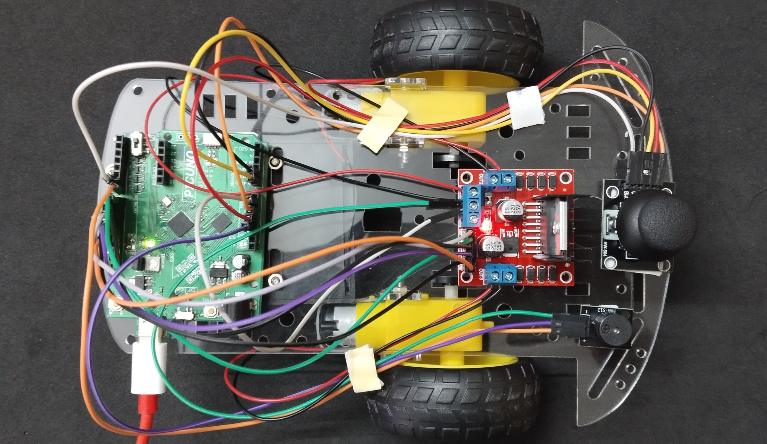
ASSEMBLY OF 2-WHEEL CHASIS KIT:
1.) Prepare the Chassis: If your chassis parts are acrylic, they often come with a protective paper or plastic film. Peel this film off all the pieces.
2.) Mount the Motors: Attach the two yellow DC motors to the main chassis plate. Use the brackets and long screws/nuts that came with the kit to secure them firmly in place.
3.) Attach the Wheels: Push the two main wheels onto the plastic shafts of the motors. They should be a snug fit.
4.) Attach the Caster Wheel: Mount the third, free-spinning wheel (the caster or ball wheel) to the other end of the chassis. This wheel acts as the front or back support and allows the robot to turn easily.
5.) Mount the Battery Holder: Use screws to attach the 4xAA battery pack at the bottom of the chassis.
6.) Mount the Electronics: Finally, mount the PICUNO, L298N motor driver, Joystick and Buzzer onto the chassis, usually using screws/double tape. Position them such that to easily run wires to the motors.
CIRCUIT DIAGRAM:
- OUT1 & OUT2: Connect these two screw terminals to the outputs for the first motor (e.g., the left wheel). Connect the two wires from one DC motor here.
- OUT3 & OUT4: Connect these two screw terminals to the outputs for the second motor (e.g., the right wheel). Connect the two wires from the other DC motor here.
- Connect the positive terminal (+) of the 4xAA battery pack to the 12V screw terminal.
- Connect the negative terminal (-) of the 4xAA battery pack to the GND screw terminal.
- Also connect the GND terminal on the L298N to a GND pin on the microcontroller to create a common ground.
- Connect the IN1 pin (Left motor) to GPIO 8.
- Connect the IN2 pin (Left motor) to GPIO 9.
- Connect the ENA pin (Left motor speed) to GPIO 10.
- Connect the IN1 pin (Right motor) to GPIO 11.
- Connect the IN2 pin (Right motor) to GPIO 12.
- Connect the ENB pin (Right motor speed) to GPIO 13.
NOTE: Remove the ENA and ENB jumpers on the L298N motor driver.
- Connect the VCC pin to 5V pin on the board.
- Connect the GND pin to GND pin on board.
- Connect the VRx pin to Analog Pin A0 (GPIO 26).
- Connect the VRy pin to Analog Pin A1 (GPIO 27).
- Connect the SW (Switch) pin to GPIO 6.
- Connect the GND (-) pin to GND pin.
- Connect the VCC (+) pin to 5V.
- Connect the Signal (S) pin to GPIO 7.
OPTIONAL: You can power the PICUNO using an external power supply (9V Battery) through DC Jack, once you have uploaded the code to the microcontroller.
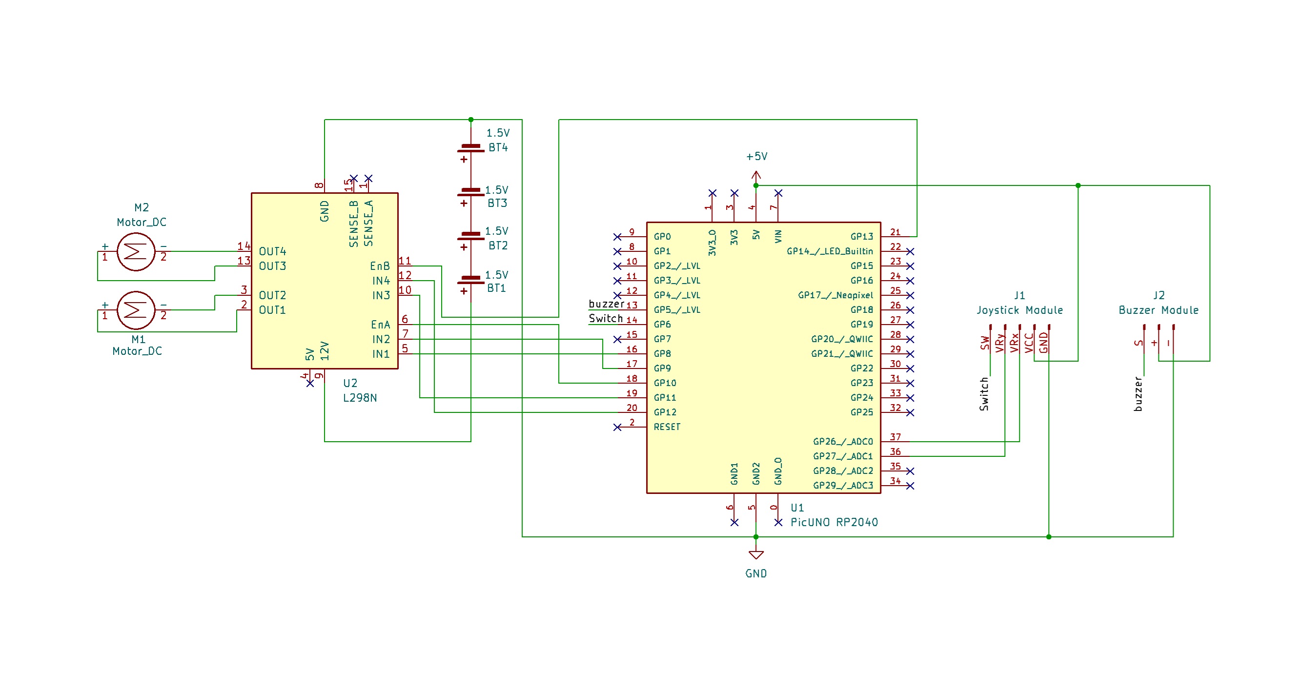
SCHEMATIC:
L298N Motor Driver:
OUT2 & OUT2 → Outputs for the Left Motor.
OUT3 & OUT4 → Outputs for the Right Motor.
12V → positive terminal (+) of 4xAA battery pack.
GND → negative terminal (-) of 4xAA battery pack → GND on PICUNO.
IN1 (Left Motor) → GPIO 8
IN2 (Left Motor) → GPIO 9
ENA (Left Motor speed) → GPIO 10
IN3 (Right Motor) → GPIO 11
IN4 (Right Motor) → GPIO 12
ENB (Right Motor) → GPIO 13
Joystick Module:
VCC → 5V
GND → GND
VRx → A0 (GPIO 26)
VRy → A1 (GPIO 27)
SW → GPIO 6
Buzzer Module:
VCC / (+) → 5V
GND / (-) → GND
Signal (S) → GPIO 7
CODE -- C:
const int L_IN1=8, L_IN2=9, L_ENA=10;
const int R_IN3=11, R_IN4=12, R_ENB=13;
const int JOY_X=A0, JOY_Y=A1, JOY_SW=6;
const int BUZZER_PIN = 7;
// --- Helper Function ---
void setMotorSpeed(char motor, int speed) {
int duty = map(abs(speed), 0, 100, 0, 255);
if (motor == 'L') {
if (speed > 0) { digitalWrite(L_IN1, HIGH); digitalWrite(L_IN2, LOW); }
else if (speed < 0) { digitalWrite(L_IN1, LOW); digitalWrite(L_IN2, HIGH); }
else { digitalWrite(L_IN1, LOW); digitalWrite(L_IN2, LOW); }
analogWrite(L_ENA, duty);
} else if (motor == 'R') {
if (speed > 0) { digitalWrite(R_IN3, HIGH); digitalWrite(R_IN4, LOW); }
else if (speed < 0) { digitalWrite(R_IN3, LOW); digitalWrite(R_IN4, HIGH); }
else { digitalWrite(R_IN3, LOW); digitalWrite(R_IN4, LOW); }
analogWrite(R_ENB, duty);
}
}
void setup() {
pinMode(L_IN1, OUTPUT); pinMode(L_IN2, OUTPUT); pinMode(L_ENA, OUTPUT);
pinMode(R_IN3, OUTPUT); pinMode(R_IN4, OUTPUT); pinMode(R_ENB, OUTPUT);
pinMode(JOY_SW, INPUT_PULLUP);
pinMode(BUZZER_PIN, OUTPUT);
Serial.begin(9600);
Serial.println("Joystick Robot Ready.");
}
void loop() {
int xValue = analogRead(JOY_X);
int yValue = analogRead(JOY_Y);
int swValue = digitalRead(JOY_SW);
// Convert 0-1023 range to a -100 to 100 range
int ySpeed = map(yValue, 0, 1023, -100, 100);
int xTurn = map(xValue, 0, 1023, -100, 100);
// --- Dead Zone Logic ---
if (abs(ySpeed) < 10) ySpeed = 0;
if (abs(xTurn) < 10) xTurn = 0;
// --- Arcade-Style Steering Logic ---
int leftSpeed = ySpeed + xTurn;
int rightSpeed = ySpeed - xTurn;
// Constrain the values to be within -100 to 100
leftSpeed = constrain(leftSpeed, -100, 100);
rightSpeed = constrain(rightSpeed, -100, 100);
setMotorSpeed('L', leftSpeed);
setMotorSpeed('R', rightSpeed);
// --- Buzzer Logic ---
if (swValue == LOW) { // Button is pressed
tone(BUZZER_PIN, 3500);
} else {
noTone(BUZZER_PIN);
}
Serial.print("X: ");
Serial.print(xValue);
Serial.print("\\t Y: ");
Serial.print(yValue);
Serial.print("\\t L_Speed: ");
Serial.print(leftSpeed);
Serial.print("\\t R_Speed: ");
Serial.print(rightSpeed);
Serial.print("\\t Button: ");
Serial.println(swValue == LOW ? "Pressed" : "Off");
delay(20);
}
analogRead(JOY_X) - This function reads the physical position of the joystick on one axis and converts it into a number between 0 and 1023.
Dead Zone Logic - The lines if (abs(ySpeed) < 10) ySpeed = 0; create a "dead zone." This prevents the robot from twitching or drifting when the joystick is released, as it rarely returns to a perfect zero position.
Arcade-Style Steering - The logic leftSpeed = ySpeed + xTurn; and rightSpeed = ySpeed - xTurn; is a standard method for mixing joystick inputs. It allows you to control both speed and turning at the same time for smooth driving.
setMotorSpeed() function - This is the core of the motor control. It takes a motor ('L' or 'R') and a speed (-100 to 100) as input. It sets the direction pins (IN1/IN2) correctly for forward or reverse and then sets the speed using analogWrite().
CODE -- PYTHON:
from machine import Pin, PWM, ADC
from time import sleep
L_IN1 = Pin(8, Pin.OUT); L_IN2 = Pin(9, Pin.OUT); L_ENA = PWM(Pin(10))
L_ENA.freq(1000)
R_IN3 = Pin(11, Pin.OUT); R_IN4 = Pin(12, Pin.OUT); R_ENB = PWM(Pin(13))
R_ENB.freq(1000)
adc_x = ADC(Pin(26))
adc_y = ADC(Pin(27))
button = Pin(6, Pin.IN, Pin.PULL_UP)
buzzer = PWM(Pin(7))
# --- Helper Function for Motor Control ---
def set_motor_speed(motor, speed):
duty = int(abs(speed) / 100 * 65535)
if motor == 'left':
if speed > 0: L_IN1.high(); L_IN2.low()
elif speed < 0: L_IN1.low(); L_IN2.high()
else: L_IN1.low(); L_IN2.low()
L_ENA.duty_u16(duty)
elif motor == 'right':
if speed > 0: R_IN3.high(); R_IN4.low()
elif speed < 0: R_IN3.low(); R_IN4.high()
else: R_IN3.low(); R_IN4.high()
R_ENB.duty_u16(duty)
# --- Main Loop ---
print("Joystick Robot Ready.")
while True:
x_val = adc_x.read_u16()
y_val = adc_y.read_u16()
# Convert joystick values from 0-65535 to a -100 to 100 range
y_speed = (y_val - 32767) / 327.67
x_turn = (x_val - 32767) / 327.67
# --- Dead Zone Logic ---
if abs(y_speed) < 10: y_speed = 0
if abs(x_turn) < 10: x_turn = 0
# --- Arcade-Style Steering Logic ---
left_speed = y_speed + x_turn
right_speed = y_speed - x_turn
# Constrain the values to be within -100 to 100
left_speed = max(-100, min(100, left_speed))
right_speed = max(-100, min(100, right_speed))
set_motor_speed('left', left_speed)
set_motor_speed('right', right_speed)
if button.value() == 0:
buzzer.freq(2500)
buzzer.duty_u16(32768)
else:
buzzer.duty_u16(0)
print(f"X: {x_val}\\t Y: {y_val}\\t L_Speed: {int(left_speed)}\\t R_Speed: {int(right_speed)}\\t Button: {'Pressed' if button.value() == 0 else 'Off'}")
sleep(0.02)
ADC(Pin(26)) - This creates an Analog-to-Digital Converter object on GPIO 26. This is necessary to read the Analog voltage signal from the joystick's X-axis.
set_motor_speed() function - This is the core of the motor control. It takes a motor ('left' or 'right') and a speed (-100 to 100) as input. It sets the direction pins (IN1/IN2) correctly for forward or reverse and then sets the speed using the PWM duty_u16() function.
Dead Zone Logic - The lines if abs(y_speed) < 10: y_speed = 0 create a "dead zone." This prevents the robot from twitching or drifting when the joystick is released, as it rarely returns to a perfect zero position.
Arcade-Style Steering - The logic left_speed = y_speed + x_turn and right_speed = y_speed - x_turn is a standard way to mix joystick inputs. It allows you to control both speed and turning simultaneously for smooth, intuitive driving.