LED Brightness Control With Rotary Encoder Module
HARDWARE REQUIRED:
- PICUNO Microcontroller board
- 1 × Rotary Encoder Module
- 1 × LED
- 1 × 220Ω resistor (current-limiting resistor)
- Jumper wires
- USB cable
DESCRIPTION:
This project demonstrates how to use a rotary encoder, a digital knob that can spin infinitely, to precisely control an output. Turning the knob clockwise increases the brightness of an LED, while turning it counter-clockwise decreases it. Pressing the encoder's built-in push-button toggles the LED on and off completely. This project is a fundamental introduction to handling digital pulse inputs for creating user interfaces.
LIBRARIES REQUIRED:
For C / Arduino IDE:
- RotaryEncoder by Matthias Hertel: Installed via the Arduino Library Manager.
- rotary_irq.py: The custom self-contained library file saved to the PICUNO board.
- The code also uses the built-in machine and time modules.
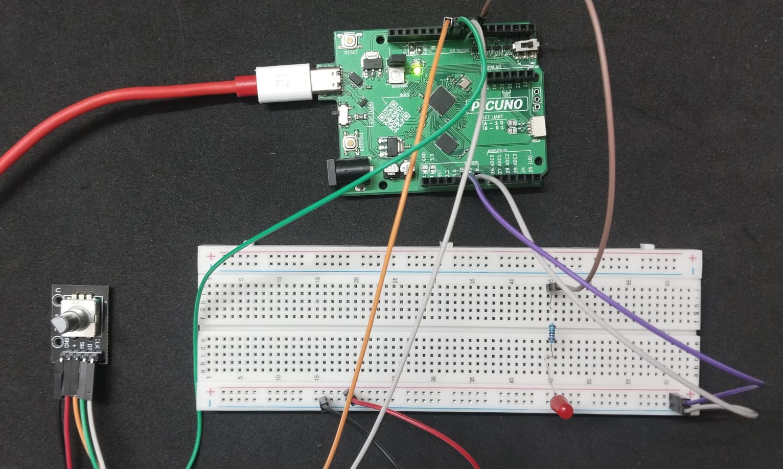
CIRCUIT DIAGRAM:
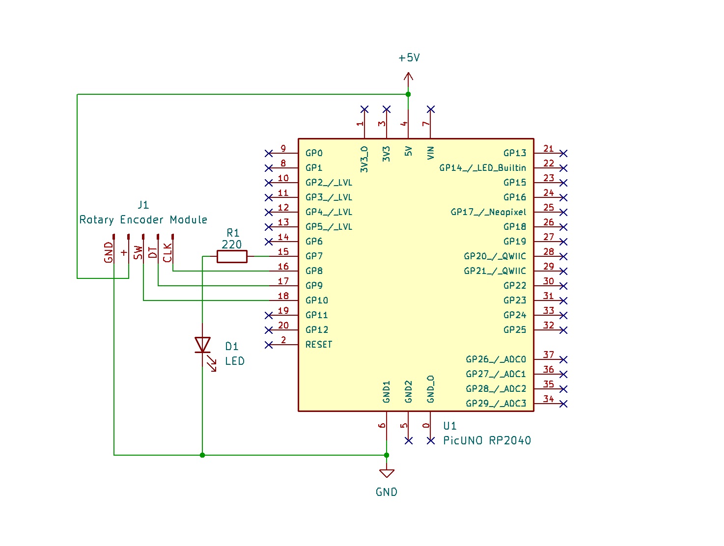
- Connect the PICUNO board to the computer using a USB cable.
- Rotary Encoder Module:
- GND → Connect to GND on PICUNO.
- + → Connect to 5V on PICUNO.
- SW (Switch) → Connect to GPIO 10.
- DT (Data) → Connect to GPIO 9.
- CLK (Clock) → Connect to GPIO 8.
- LED:
- Connect the longer leg (anode) of the LED to GPIO 7 through 220Ω resistor.
- Connect the shorter leg (cathode) of the LED to GND.
SCHEMATIC:
Rotary Encoder + → 5V
Rotary Encoder GND → GND
Rotary Encoder SW → GPIO 10
Rotary Encoder DT → GPIO 9
Rotary Encoder CLK → GPIO 8
GPIO 7 → 220Ω Resistor → LED Anode
LED Cathode → GND
CODE -- C:
#include <RotaryEncoder.h>
// Define the pins for the rotary encoder
#define PIN_CLK 8
#define PIN_DT 9
#define PIN_SW 10
// Define the pin for the LED (must be a PWM pin)
#define LED_PIN 7
// Create an encoder object
RotaryEncoder encoder(PIN_DT, PIN_CLK, RotaryEncoder::LatchMode::FOUR3);
// Variables to store state
int brightness = 128;
bool ledOn = true;
bool lastButtonState = HIGH;
int oldBrightness = -1;
void setup() {
pinMode(LED_PIN, OUTPUT);
pinMode(PIN_SW, INPUT_PULLUP);
Serial.begin(9600);
Serial.println("Rotary Encoder Test Ready!");
Serial.println("LED State: ON");
}
void loop() {
// Check the encoder rotation
encoder.tick();
int newPos = encoder.getPosition();
if (newPos > 0) {
brightness += 5;
encoder.setPosition(0);
} else if (newPos < 0) {
brightness -= 5;
encoder.setPosition(0);
}
brightness = constrain(brightness, 0, 255);
if (brightness != oldBrightness) {
Serial.print("Brightness: ");
Serial.println(brightness);
oldBrightness = brightness;
}
// Check the button press
bool currentButtonState = digitalRead(PIN_SW);
if (currentButtonState == LOW && lastButtonState == HIGH) {
ledOn = !ledOn;
if (ledOn) {
Serial.println("LED State: ON");
} else {
Serial.println("LED State: OFF");
}
delay(100);
}
lastButtonState = currentButtonState;
// Update the LED
if (ledOn) {
analogWrite(LED_PIN, brightness);
} else {
analogWrite(LED_PIN, 0);
}
}
encoder.tick() - This must be called in the loop to allow the library to check the sensor pins.
encoder.getPosition() - Returns the direction the knob was turned (>0 for one way, <0 for the other).
constrain() - Keeps the brightness variable from going above 255 or below 0.
digitalRead(PIN_SW) - Checks if the built-in button on the encoder is pressed.
analogWrite() - Sets the LED's brightness using PWM.
CODE -- PYTHON:
from machine import Pin, PWM
import time
from rotary_irq import RotaryIRQ
# Define the pins
PIN_CLK = 8
PIN_DT = 9
PIN_SW = 10
LED_PIN = 7
# Setup the LED with PWM
led = PWM(Pin(LED_PIN))
led.freq(1000) # Set PWM frequency
# Setup the encoder
encoder = RotaryIRQ(pin_num_clk=PIN_CLK,
pin_num_dt=PIN_DT,
min_val=0,
max_val=255,
reverse=False,
range_mode=RotaryIRQ.RANGE_BOUNDED)
# Setup the switch button
switch = Pin(PIN_SW, Pin.IN, Pin.PULL_UP)
# Variables to store state
led_on = True
last_switch_state = switch.value()
last_encoder_val = encoder.value()
print("Ready to control LED...")
while True:
# --- Check the encoder rotation ---
current_encoder_val = encoder.value()
if last_encoder_val != current_encoder_val:
last_encoder_val = current_encoder_val
print("Brightness:", current_encoder_val)
# Scale 0-255 brightness to 0-65535 duty cycle for PWM
duty = int(current_encoder_val * 65535 / 255)
if led_on:
led.duty_u16(duty)
# --- Check the button press ---
current_switch_state = switch.value()
if current_switch_state == 0 and last_switch_state == 1:
led_on = not led_on
if led_on:
print("LED ON")
# Restore brightness when turned back on
duty = int(current_encoder_val * 65535 / 255)
led.duty_u16(duty)
else:
print("LED OFF")
led.duty_u16(0)
time.sleep_ms(200)
last_switch_state = current_switch_state
from rotary_irq import RotaryIRQ - Imports the necessary class from the library file.
encoder = RotaryIRQ(...) - Creates the encoder object, setting its range from 0 to 255.
encoder.value() - Reads the current position (0-255) that the library is tracking.
duty = int(...) - Scales the 0-255 encoder value to the 16-bit PWM duty cycle range for the LED.
switch.value() - Checks if the built-in button is being pressed to toggle the LED on or off.