Magnetic Door Alarm
HARDWARE REQUIRED:
- PICUNO Microcontroller board
- 1 × HW-497 Mini Reed Switch
- 1 × HW-477 Two-colour LED Module
- 1 × Buzzer Module
- Jumper wires
- USB cable
DESCRIPTION:
This project creates a simple but effective security alarm for a door or window. A reed switch is placed on the doorframe, and a magnet is placed on the door. When the door is closed, the magnet keeps the switch activated, and a green LED indicates that the system is armed and secure. When the door is opened, the magnet moves away, triggering the reed switch. This immediately sounds a high-pitched alarm through a buzzer and switches the indicator light to a flashing red LED, providing a clear visual and audible alert of the breach.
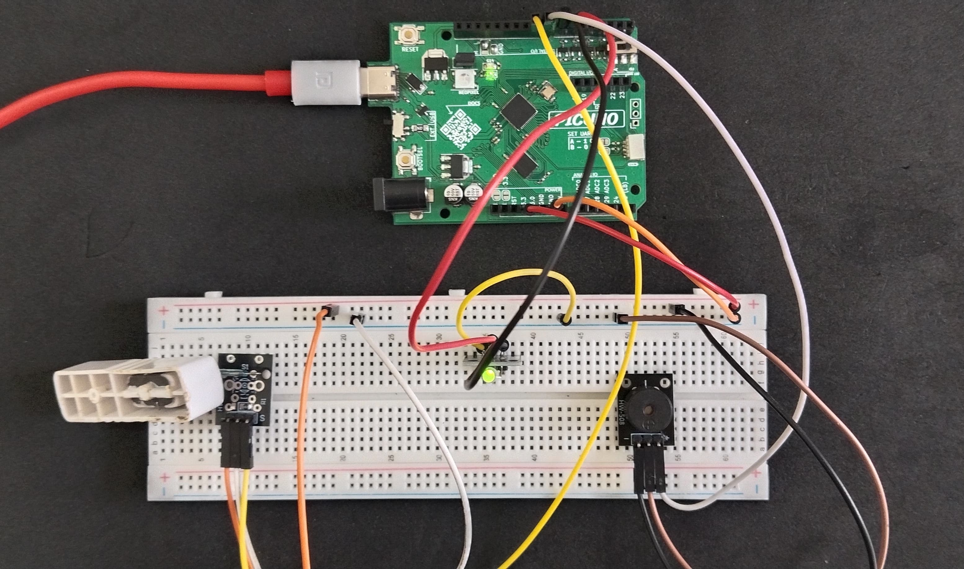
CIRCUIT DIAGRAM:
- Connect the VCC (+) pin to 5V pin on the board.
- Connect the GND (-) pin to GND pin on board.
- Connect the Signal (S) pin to GPIO 9.
- Connect the GND (-) pin to GND pin.
- Connect the VCC (+) pin to 5V.
- Connect the Signal (S) pin to GPIO 8.
- Connect the GND (-) pin to GND pin on board.
- Connect the Red (R) LED pin to GPIO 6.
- Connect the Green (G) LED pin to GPIO 7.
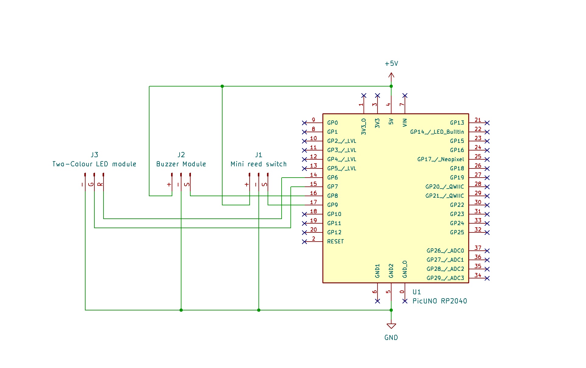
SCHEMATIC:
Mini Reed Switch:
GND / (-) → GND
VCC / (+) → 5V
SIGNAL / (S) → GPIO 9
Buzzer Module:
VCC / (+) → 5V
GND / (-) → GND
Signal (S) → GPIO 8
Two-colour LED module:
GND / (-) → GND
Red LED / (R) → GPIO 6
Green LED / (G) → GPIO 7
CODE -- C:
pinMode(REED_SWITCH_PIN, INPUT) - This command configures the pin connected to the reed switch as an input, allowing the board to receive a HIGH or LOW signal from it.
digitalRead(REED_SWITCH_PIN) - This function reads the current state of the reed switch. It will return HIGH (a value of 1) if the magnet is close (door closed) or LOW (a value of 0) if the magnet is far away (door open).
if (switchState == HIGH) - This is the main decision-making part of the code. It checks if the door is closed. If it is, the code inside this block runs, which turns the green LED on and keeps the buzzer silent.
else - If the if condition is false (meaning the door is open), the code inside the else block runs. This turns the red LED on and activates the alarm.
tone(BUZZER_PIN, 2000) - This command generates a continuous sound on the buzzer at a high pitch (2000 Hz) to create an audible alarm. noTone() is used to turn it off.
CODE -- PYTHON:
Pin(9, Pin.IN) - Configures the GPIO pin connected to the reed switch as a digital input to read its HIGH or LOW state.
switch_state = reed_switch.value() - Reads the current state of the sensor. It returns 1 (HIGH) if the magnet is close (door closed) and 0 (LOW) if the magnet is far (door open).
if switch_state == 1: - This is the main logic. It checks if the door is closed and sets the LED to green.
else: - If the condition is false (meaning the door is open), it activates the alarm by turning the red LED on and sounding the buzzer.
buzzer.duty_u16(32768) - This command sets the PWM duty cycle to 50%, which provides the maximum volume for a buzzer.