Motor Speed Tachometer
HARDWARE REQUIRED:
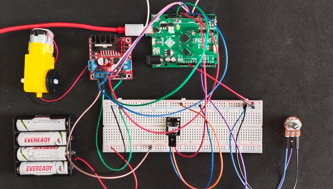
- PICUNO Microcontroller board
- 1 × DC Motor with encoder disk (20 shafts)
- 1 × 298N Motor Driver
- 1 × 10kΩ Potentiometer
- 1 × Light Blocking sensor
- 1 × 4xAA Battery pack (with fresh or rechargeable batteries)
- Jumper wires
- USB cable
DESCRIPTION:
This project creates a functional tachometer, a device that measures the rotational speed of a motor in Revolutions Per Minute (RPM).
A small disk with one or more slots is attached to the motor shaft. This disk spins through the Light Blocking Sensor's slot. Each time a slot in the disk passes through the sensor, the infrared beam is unblocked, generating a digital pulse. The PICUNO uses hardware interrupts for precise pulse counting. It counts the number of pulses over a set period, calculates the RPM, and prints the result to the Serial Monitor in real-time. A potentiometer is used as a throttle to control the motor's speed, allowing you to instantly see how the RPM changes.
A small disk with one or more slots is attached to the motor shaft. This disk spins through the Light Blocking Sensor's slot. Each time a slot in the disk passes through the sensor, the infrared beam is unblocked, generating a digital pulse. The PICUNO uses hardware interrupts for precise pulse counting. It counts the number of pulses over a set period, calculates the RPM, and prints the result to the Serial Monitor in real-time. A potentiometer is used as a throttle to control the motor's speed, allowing you to instantly see how the RPM changes.
CIRCUIT DIAGRAM:

- OUT1 & OUT2: Connect these two screw terminals to the outputs for the DC Motor. Connect the two wires from one DC motor here.
- Connect the positive terminal (+) of the 4xAA battery pack to the 12V screw terminal.
- Connect the negative terminal (-) of the 4xAA battery pack to the GND screw terminal.
- Also connect the GND terminal on the L298N to a GND pin on the microcontroller to create a common ground.
- Connect the IN1 pin (Left motor) to GPIO 8.
- Connect the IN2 pin (Left motor) to GPIO 9.
- Connect the ENA pin (Left motor speed) to GPIO 10.
- Connect the IN1 pin (Right motor) to GPIO 11.
- Connect the IN2 pin (Right motor) to GPIO 12.
- Connect the ENB pin (Right motor speed) to GPIO 13.
NOTE: Remove the ENA and ENB jumpers on the L298N motor driver.
- Connect outer terminals of the potentiometer to VCC and GND, centre terminal to Analog pin A0 (Pin 26 in PICUNO)
- Connect the GND (-) pin to GND on board.
- Connect the VCC (+) pin to 5V on board.
- Connect the Signal (S) pin to GPIO 6.
SCHEMATIC:
L298N Motor Driver:
OUT2 & OUT2 → Outputs for the DC Motor.
12V → positive terminal (+) of 4xAA battery pack.
GND → negative terminal (-) of 4xAA battery pack → GND on PICUNO.
IN1 (Left Motor) → GPIO 8
IN2 (Left Motor) → GPIO 9
ENA (Left Motor speed) → GPIO 10
IN3 (Right Motor) → GPIO 11
IN4 (Right Motor) → GPIO 12
ENB (Right Motor) → GPIO 13
10kΩ Potentiometer:
Outer Terminals → VCC, GND
Centre Terminal → A0 (GPIO 26)
Light Blocking sensor:
GND / (-) → GND
VCC / (+) → 5V
Signal / (S) → GPIO 6
CODE -- C:
countPulse() function - This is the Interrupt Service Routine (ISR). It's a special, high-priority function that the microcontroller pauses its main loop() to run immediately whenever the sensor detects a pulse. Its only job is to increment the pulseCount.
attachInterrupt(...) - It tells the PICUNO to constantly monitor the SENSOR_PIN and to automatically run the countPulse() function every time it detects a FALLING edge (the signal going from high to low).
if (millis() - lastTime >= 1000) - The millis() function returns the number of milliseconds since the board started. This line checks if one second has passed without using a delay() command, which would freeze the program and cause pulses to be missed.
detachInterrupt() / attachInterrupt() - Before reading and resetting pulseCount, the interrupt is temporarily detached. This ensures the ISR can't change the value while the main loop is in the middle of a calculation. After the calculation, the interrupt is re-attached to resume counting.
CODE -- PYTHON:
count_pulse(pin) function - This is the Interrupt Service Routine (ISR). It's a special, high-priority function that runs automatically the instant a pulse is detected by the sensor pin. The global pulse_count line is essential, allowing this function to modify the main pulse_count variable.
sensor_pin.irq(...) - This line sets up the hardware interrupt. It tells the PicUNO to monitor the sensor_pin and, when it detects a FALLING edge (the signal going from high to low as a slot passes), to immediately run the count_pulse function.
if time.ticks_diff(...) >= 1000: - This is a non-blocking timer. It checks if at least one second has passed since the last calculation without using time.sleep(), which would freeze the program.
machine.disable_irq() / machine.enable_irq() - This block temporarily "pauses" all interrupts just long enough to safely copy the pulse_count value and then reset it to zero.