Real-Time Clock With I2C LCD Display
HARDWARE REQUIRED:
- PICUNO Microcontroller board
- 1 × 16x2 I2C LCD Display
- 1 × DS1302 Real Time Clock Module
- Jumper wires
- USB cable
- 9V Battery with a snap connector (to power the board via the DC Jack)
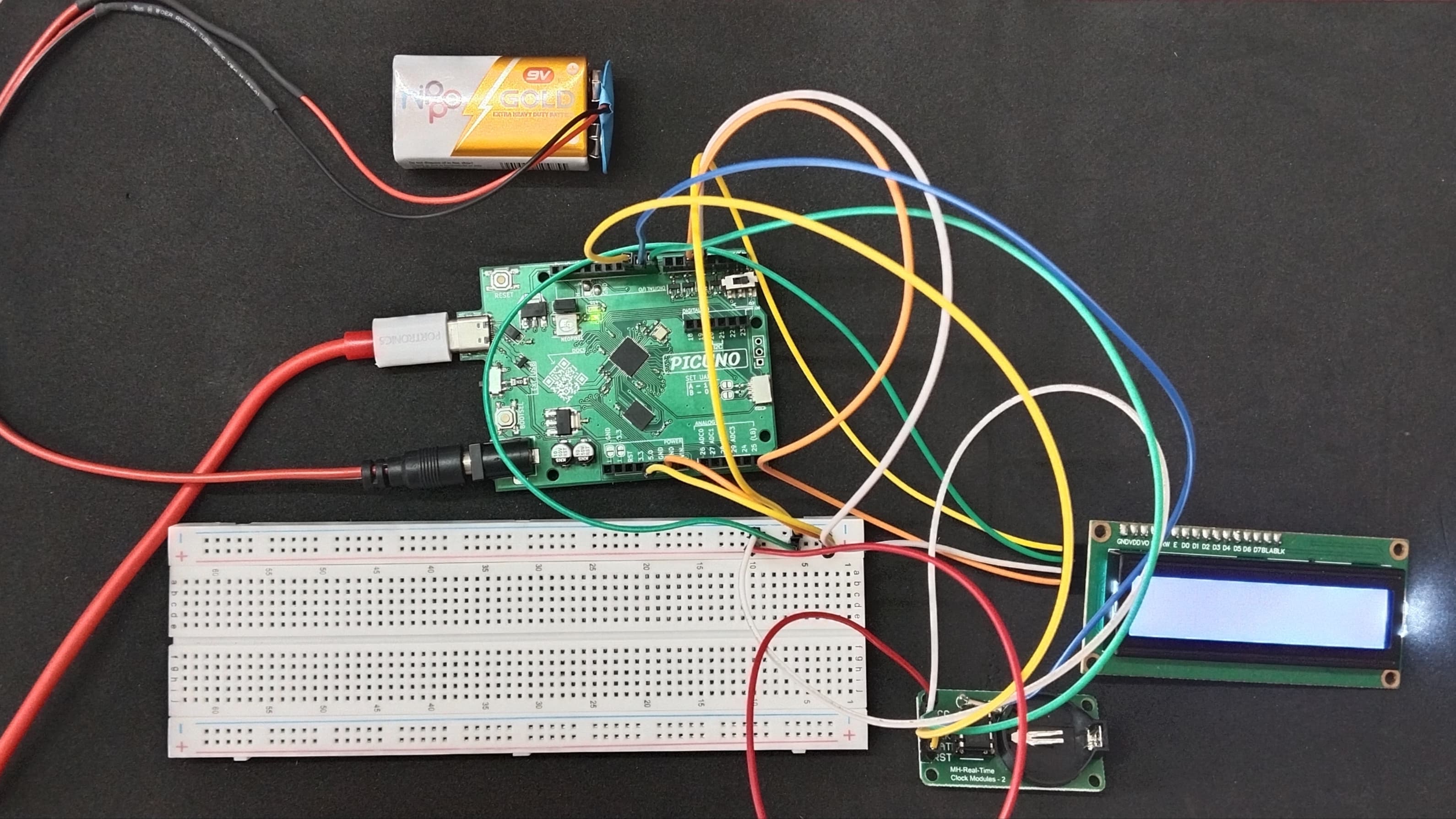
DESCRIPTION:
This project creates a functional digital clock using a DS1302 RTC module and an I2C LCD. The PICUNO continuously fetches the current time from the RTC module and formats it into a "DD/MM/YYYY" and "HH:MM:SS" display on the LCD screen.
NOTE:
This project is documented without the optional CR2032 backup battery. This means the clock will keep time perfectly while the board is powered on, but will forget and reset every time the power is disconnected.
LIBRARIES REQUIRED:
For C / Arduino IDE:
- Ds1302 by Rafa Couto: The driver library for the DS1302 RTC Module.
- Wire.h: Manages I2C communication (usually included by default).
- LiquidCrystal_I2C.h: The driver library for the I2C LCD module.
- ds1302.py: The custom library file for the RTC, saved to the PICUNO board.
- i2c_lcd.py: The custom library file saved to the PICUNO board.
- The code also uses the built-in machine and time modules.
CIRCUIT DIAGRAM:
- Connect the LCD Module's GND pin to a GND pin on board.
- Connect the LCD Module's VCC pin to the 5V pin on board.
- Connect the LCD Module's SDA pin GPIO 4 (SDA Pin on PICUNO).
- Connect the LCD Module's SCL pin GPIO 5 (SCL Pin on PICUNO).
- DS1302 RTC Module:
- Connect the VCC pin to 5V pin on the board.
- Connect the GND pin to GND pin on board.
- Connect the CLK pin to GPIO 8.
- Connect the DAT pin to GPIO 9.
- Connect the RST pin to GPIO 10.
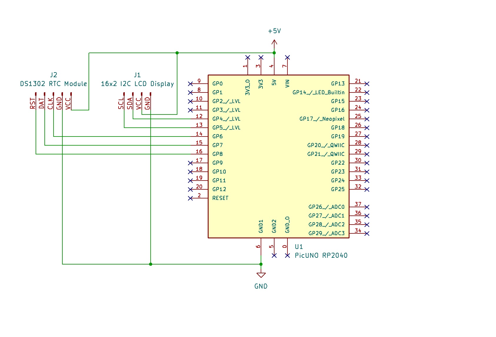
SCHEMATIC:
LCD VCC → 5V
LCD GND → GND
LCD SDA → GPIO 4 (Board SDA Pin)
LCD SCL → GPIO 5 (Board SCL Pin)
RTC VCC → 5V
RTC GND → GND
RTC CLK → GPIO 8
RTC DAT → GPIO 9
RTC RST → GPIO 10
CODE -- C:
#include <Wire.h>
#include <LiquidCrystal_I2C.h>
#include <Ds1302.h>
LiquidCrystal_I2C lcd(0x27, 16, 2);
const int RST_PIN = 10;
const int DAT_PIN = 9;
const int CLK_PIN = 8;
Ds1302 rtc(RST_PIN, CLK_PIN, DAT_PIN);
void setup() {
lcd.init();
lcd.backlight();
rtc.init();
// --- SET THE TIME (Run this part only ONCE) ---
// If the clock isn't running, this will set it.
// After setting it once, it will not run again unless the module loses all power.
if (rtc.isHalted()) {
// Create a DateTime object with the current time
Ds1302::DateTime dt = {
.year = 25, // Year (00-99) -> 2025
.month = 7, // Month
.day = 3, // Day
.hour = 17, // Hour (24-hour format)
.minute = 10, // Minute
.second = 0, // Second
.dow = 5 // Day of week (1=Mon... 5=Thu... 7=Sun)
};
// Set the time on the RTC module
rtc.setDateTime(&dt);
}
}
void loop() {
Ds1302::DateTime now;
rtc.getDateTime(&now);
lcd.setCursor(0, 0);
if (now.day < 10) lcd.print("0");
lcd.print(now.day);
lcd.print("/");
if (now.month < 10) lcd.print("0");
lcd.print(now.month);
lcd.print("/");
lcd.print(now.year + 2000);
lcd.setCursor(0, 1);
if (now.hour < 10) lcd.print("0");
lcd.print(now.hour);
lcd.print(":");
if (now.minute < 10) lcd.print("0");
lcd.print(now.minute);
lcd.print(":");
if (now.second < 10) lcd.print("0");
lcd.print(now.second);
// Wait one second before updating
delay(1000);
}
Ds1302 rtc(...) - Creates the RTC object using the pins you have connected.
if (rtc.isHalted()) - It only runs if the clock has lost power and stopped.
rtc.setDateTime(&dt) - This command sends the time and date you specify to the clock chip to set it.
rtc.getDateTime(&now) - In the main loop, this command fetches the current time from the chip.
lcd.print(now.hour) - After getting the time, we print the individual parts (like hour, minute, etc.) to the LCD.
CODE -- PYTHON:
from machine import Pin, I2C
import time
from i2c_lcd import I2cLcd
from ds1302 import DS1302
i2c = I2C(0, scl=Pin(5), sda=Pin(4))
lcd = I2cLcd(i2c, 0x27, 2, 16)
rtc = DS1302(Pin(8),Pin(9),Pin(10)) # (CLK, DAT, RST)
# --- SET THE TIME (Run ONCE) ---
# Uncomment the line below, set the current time, run the script once,
# then comment it out again and save the file.
# Format: (Year, Month, Day, Weekday(1-7), Hour, Minute, Second)
# rtc.date_time((2025, 7, 3, 4, 17, 21, 0))
while True:
(year, month, day, weekday, hour, minute, second) = rtc.date_time()
# Format the time and date strings
time_string = f"{hour:02d}:{minute:02d}:{second:02d}"
date_string = f"{day:02d}/{month:02d}/{year}"
lcd.move_to(0, 0)
lcd.putstr(date_string)
lcd.move_to(0, 1)
lcd.putstr(time_string)
time.sleep(1)
rtc = DS1302(...) - Creates the RTC object and tells the library which pins are being used.
rtc.date_time((...)) - This single command is used to set the time when you provide values inside the parentheses.
rtc.date_time() - When called with empty parentheses, it gets the time from the module and returns all the values at once.
f"{hour:02d}" - This is an f-string used to format the numbers, adding a leading zero if the number is less than 10.