Scheduled Appliance Controller
HARDWARE REQUIRED:
- PICUNO Microcontroller board
- 1 × 16x2 I2C LCD Display
- 1 × DS1302 Real Time Clock Module
- 1 × 5V Relay Module
- 1 × LED
- 1 × 220Ω resistor (Current-limiting resistor)
- Jumper wires
- USB cable
- 1 × 4xAA Battery pack (with fresh or rechargeable batteries)
DESCRIPTION:
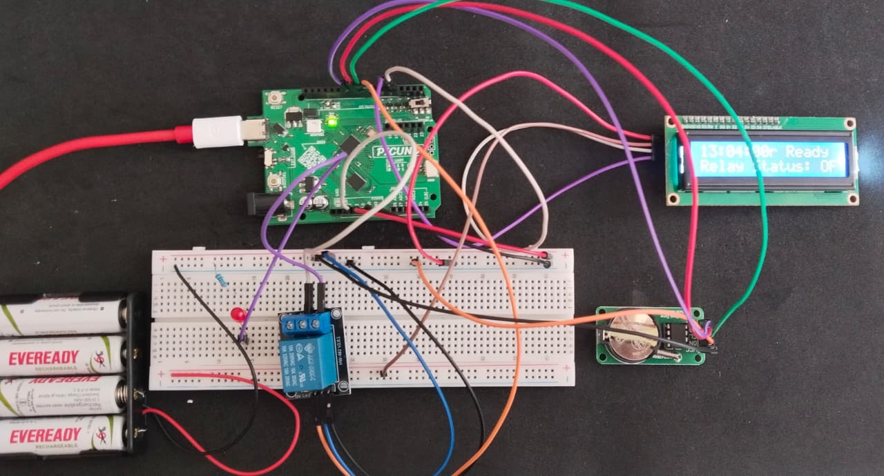
This project creates a simple but effective smart timer, like those used for home appliances. The system uses a DS1302 Real-Time Clock (RTC) module to keep accurate track of the current time.
A user can define a specific "ON" time and "OFF" time directly in the code. The PicUNO continuously checks the time from the RTC and compares it to the schedule. When the current time matches the "ON" time, it activates a relay module. When the "OFF" time is reached, it deactivates the relay. The relay's switched terminals can control an external circuit, represented here by an LED. An I2C LCD provides a constant, real-time display of the current time and the relay's status (ON/OFF).
LIBRARIES REQUIRED:
For C / Arduino IDE:
Ds1302 by Rafa Couto: The driver library for the DS1302 RTC Module.
Wire.h: Manages I2C communication (usually included by default).
LiquidCrystal_I2C.h: The driver library for the I2C LCD module.
For Micropython / Thonny IDE:
ds1302.py: The custom library file for the RTC, saved to the PICUNO board.
i2c_lcd.py: The custom library file saved to the PICUNO board.
The code also uses the built-in machine and time modules.
CIRCUIT DIAGRAM:
- Connect the LCD Module's GND pin to a GND pin on board.
- Connect the LCD Module's VCC pin to positive terminal (+) of the 4xAA Battery Pack.
- Connect the LCD Module's SDA pin GPIO 4 (SDA Pin on PICUNO).
- Connect the LCD Module's SCL pin GPIO 5 (SCL Pin on PICUNO).
- Connect the negative terminal (-) of the 4xAA Battery Pack to GND pin on PICUNO board to create common ground.
- Connect the VCC pin to 5V pin on the board.
- Connect the GND pin to GND pin on board.
- Connect the CLK pin to GPIO 8.
- Connect the DAT pin to GPIO 9.
- Connect the RST pin to GPIO 10.
- Connect the GND pin to a GND pin on PICUNO.
- Connect the VCC pin to the 5V pin on PICUNO.
- Connect the IN (Signal) pin to GPIO 7.
- Connect the COM (Common) Screw terminal on the relay to 3.3V.
- Connect the NO (Normally Open) Screw terminal on the relay to longer leg (anode) of the LED.
- Connect the shorter leg (cathode) of the LED to one end of 220Ω resistor.
- Connect the other end of the resistor to GND.
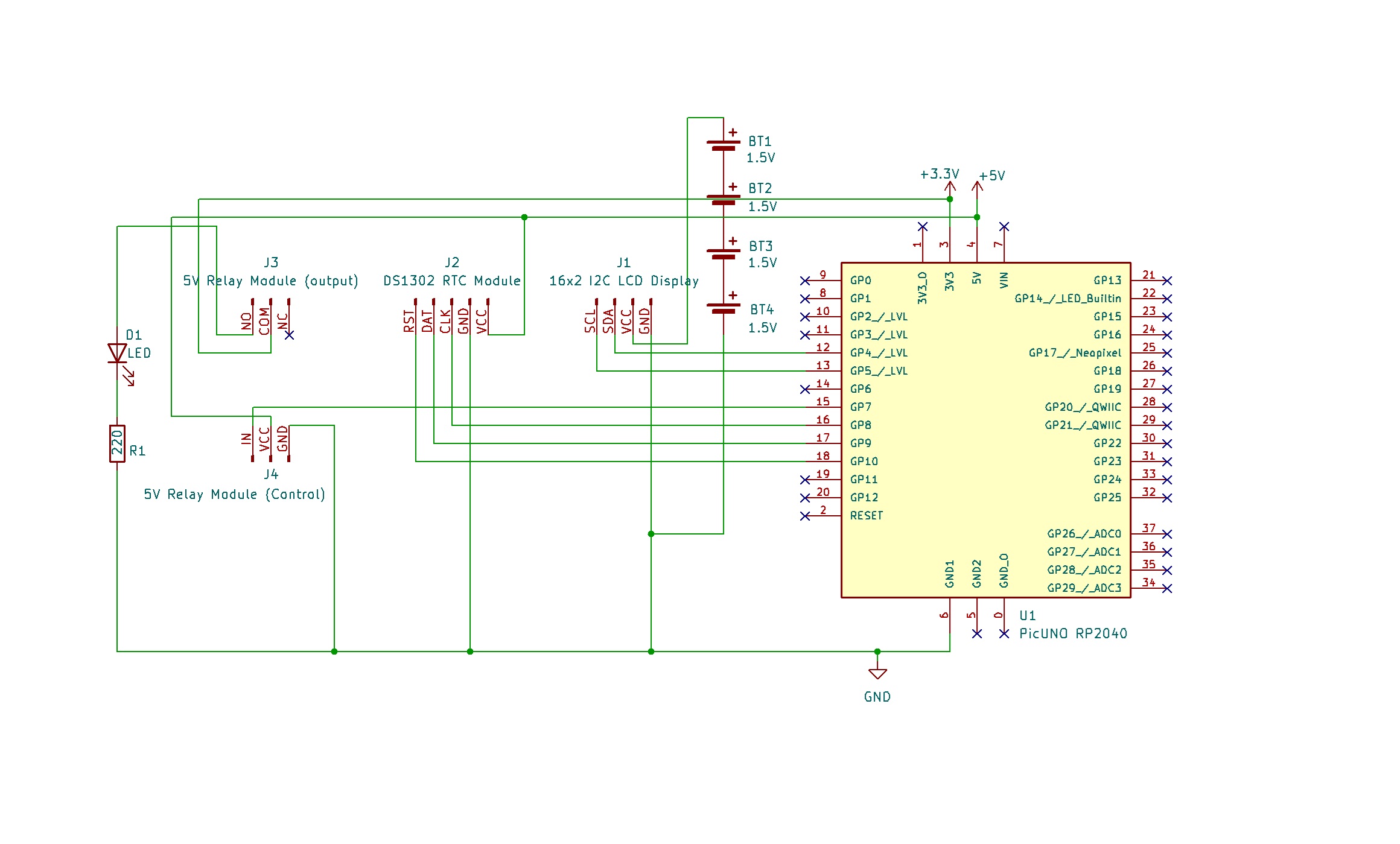
SCHEMATIC:
LCD VCC → 5V
LCD GND → GND
LCD SDA → GPIO 4 (Board SDA Pin)
LCD SCL → GPIO 5 (Board SCL Pin)
RTC VCC → 5V
RTC GND → GND
RTC CLK → GPIO 8
RTC DAT → GPIO 9
RTC RST → GPIO 10
Relay VCC → 5V
Relay GND → GND
Relay IN → GPIO 7
Relay COM → 3.3V
Relay NO → anode of LED
Cathode of LED → 220Ω resistor → GND
CODE -- C:
Ds1302 rtc(RST_PIN, CLK_PIN, DAT_PIN); - This creates the RTC object. Note the specific pin order required by this library: Reset, Clock, Data.
if (rtc.isHalted()) - The code to set the time will only run if the RTC chip has lost all power and its internal clock has stopped. This prevents the time from being reset every time you power on the PicUNO.
rtc.setDateTime(&dt); - This is the command used to send the DateTime structure to the RTC module to set its time.
rtc.getDateTime(&now); - In the main loop, this command fetches the current time from the RTC and stores it in the now variable. You can then access the parts of the time with now.hour, now.minute, etc.
CODE -- PYTHON:
rtc.date_time((...)) - This is the one-time command used to set the clock. You should uncomment it, fill in the current time, run the script once to set the RTC, and then comment it out again.
if current_time_tuple == ON_TIME: - This is the core logic of the scheduler. It directly compares the current time with the target "ON" time. If they match exactly, it activates the relay.
f"{hour:02d}" - This is a Python f-string used for formatting. The :02d part tells it to format the number as a 2-digit decimal, adding a leading zero if necessary (e.g., 7 becomes 07).