Servo Motor Control Using Potentiometer
HARDWARE REQUIRED:
- PICUNO Microcontroller board
- 1 × SG90 Servo Motor
- 1 × 10kΩ Potentiometer
- 1 × 4xAA Battery Pack (for external power supply)
- Jumper wires
- USB cable
DESCRIPTION:
This project demonstrates a fundamental principle of physical computing: using an Analog sensor to control a physical output. By turning the knob of a potentiometer, the user can precisely control the rotational angle of a servo motor in real-time. The microcontroller reads the changing voltage from the potentiometer, maps that reading to a 0 to 180 degree range, and sends the corresponding command to the servo. This project is a core building block for creating robotic arms, steering mechanisms, or any system that requires precise manual control.
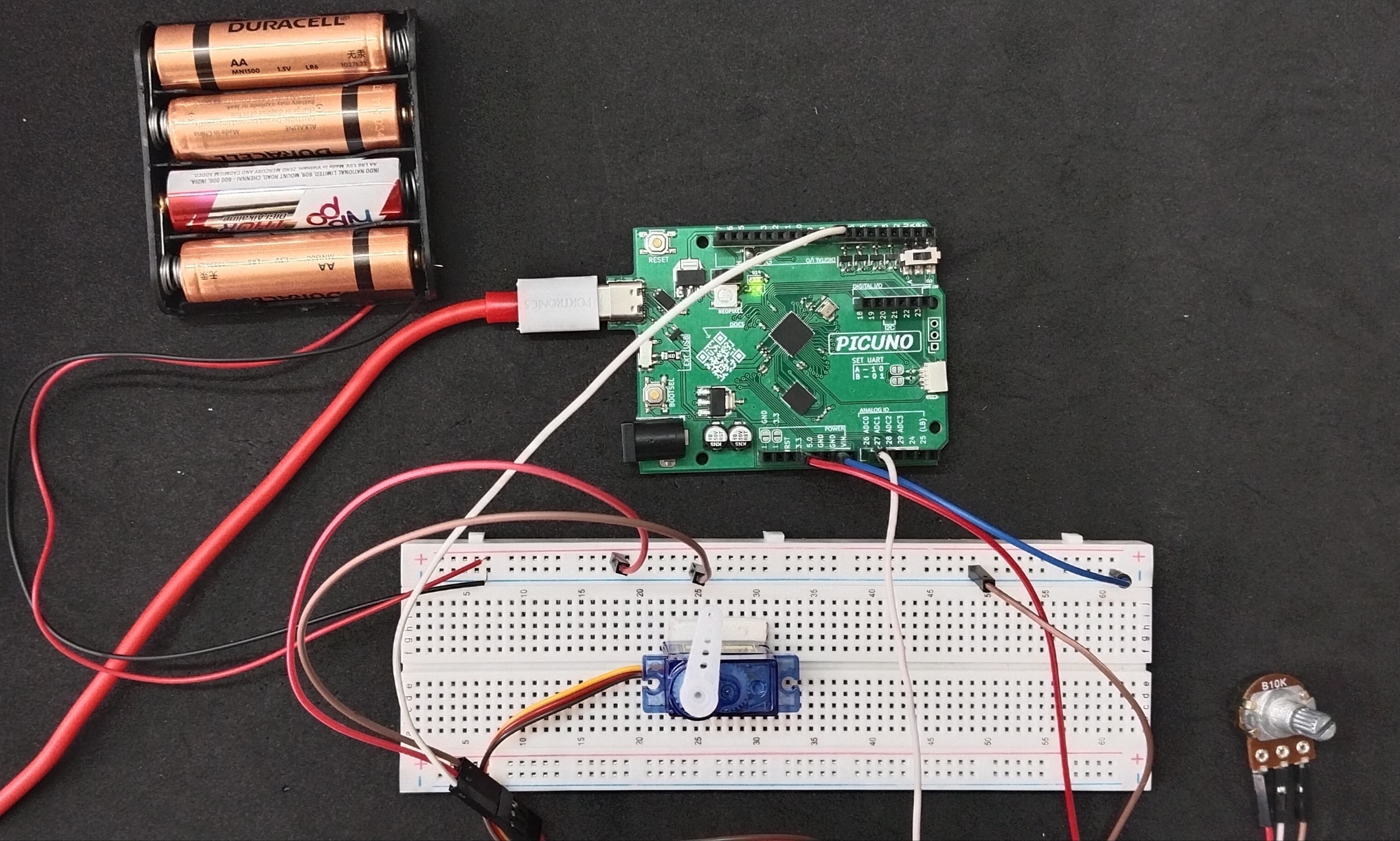
CIRCUIT DIAGRAM:
- Connect the Servo's VCC (Red) pin to the Positive (+) terminal of the 4xAA Battery Pack.
- Connect the Servo's GND (Brown) pin to GND.
- Connect the Servo's Signal (Yellow) pin to GPIO 8.
- Connect outer terminals of the potentiometer to VCC and GND, centre terminal to Analog pin A0 (GPIO 26)
- Connect the Negative (-) terminal of the 4xAA Battery Pack to GND pin on the PICUNO board to create a common ground connection.
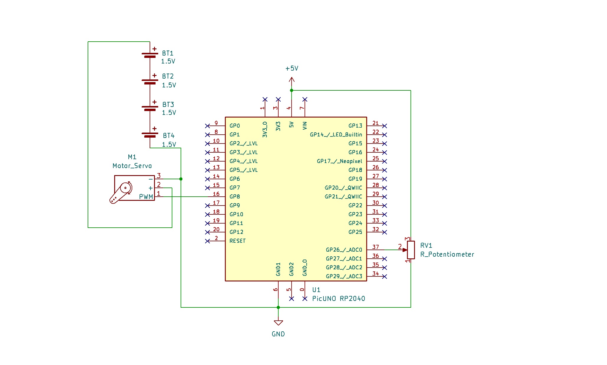
SCHEMATIC:
Servo Motor:
VCC (Red Wire) → 4xAA Battery Pack (+)
GND (Brown Wire) → GND
Signal (Yellow Wire) → GPIO 18
Potentiometer:
Potentiometer Outer Terminals → VCC, GND
Potentiometer Centre Terminal → A0
Common Ground Connection:
4xAA Battery Pack (-) → PICUNO Board GND
CODE -- C:
#include <Servo.h>
const int POT_PIN = A0;
const int SERVO_PIN = 8;
Servo myServo;
void setup() {
Serial.begin(9600);
// 500µs for min (0 degrees) and 2500µs for max (180 degrees)
myServo.attach(SERVO_PIN, 500, 2500);
Serial.println("Servo Control Initialized with custom range.");
}
void loop() {
int potValue = analogRead(POT_PIN);
int angle = map(potValue, 0, 1023, 0, 180);
myServo.write(angle);
Serial.print("Pot Value: ");
Serial.print(potValue);
Serial.print(" => Servo Angle: ");
Serial.println(angle);
delay(20);
}
#include <Servo.h> - This line includes the built-in Arduino library that makes controlling servo motors simple.
analogRead(POT_PIN) - This function reads the voltage from the specified Analog pin and returns a number between 0 (for 0 volts) and 1023 (for the maximum voltage).
myServo.attach(SERVO_PIN, 500, 2500) – To get the full 180-degree motion in Arduino by overriding the defaults.
map(value, fromLow, fromHigh, toLow, toHigh) - A convenient function that scales a number from one range to another. Here, it converts the 0-1023 reading from the potentiometer into a 0-180 degree angle for the servo.
myServo.write(angle) - This is the command that tells the servo to move to the specified angle.
CODE -- PYTHON:
from machine import Pin, ADC, PWM
from time import sleep
pot_adc = ADC(Pin(26))
servo_pwm = PWM(Pin(8))
servo_pwm.freq(50)
def map_value(x, in_min, in_max, out_min, out_max):
return (x - in_min) * (out_max - out_min) // (in_max - in_min) + out_min
print("Potentiometer Servo Control Ready")
while True:
pot_value = pot_adc.read_u16()
angle = map_value(pot_value, 0, 65535, 0, 180)
duty = map_value(angle, 0, 180, 1350, 8350)
servo_pwm.duty_u16(duty)
print(f"Pot Value: {pot_value}, Angle: {angle}")
sleep(0.02)
machine.PWM(Pin(15)) - This creates a Pulse Width Modulation object on the specified pin, which is necessary for controlling servos.
servo_pwm.freq(50) - This sets the timing frequency of the PWM signal to 50 Hz, which is the standard for almost all hobby servos.
pot_adc.read_u16() - Reads the Analog value as a 16-bit number, ranging from 0 to 65535.
servo_pwm.duty_u16(duty_cycle) - This is the function that commands the servo. It works by changing the duration of the electrical pulse (the "duty cycle") sent to the servo's signal wire, which the servo interprets as a specific angle to move to.